Nissan Versa (N17): Side air bag (satellite) sensor
Removal and Installation
Side air bag (satellite) sensor
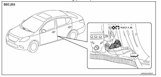
1. Side air bag (satellite) sensor harness slide
double locking type connector  Front
Front
Front door (satellite) sensor
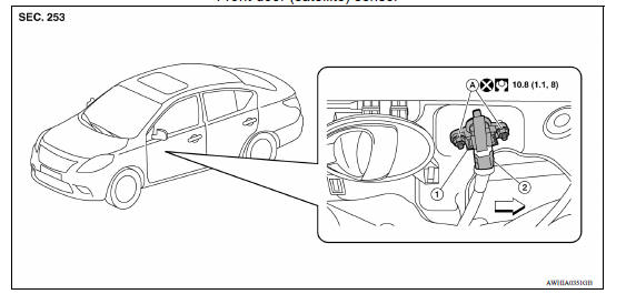
1. Front door (satellite) sensor harness
connector
2. Front door (satellite) sensor A. Front door (satellite) sensor nuts
Front
WARNING:
- Before servicing, turn ignition switch OFF, disconnect both battery terminals and wait at least three minutes.
- Do not use air tools or electric tools for servicing.
CAUTION:
- Do not use old nuts after removal; replace with new nuts.
- Do not cause impact to the side air bag (satellite) sensor by dropping etc. Replace the side air bag (satellite) sensor if it has been dropped or sustained an impact.
- Replace both the side air bag (satellite) sensor and front door (satellite) sensor of a deployed SRS front side air bag and deployed SRS side curtain air bag.
REMOVAL - SIDE AIR BAG (SATELLITE) SENSOR
- Disconnect the battery negative and positive terminals and wait at least three minutes. Refer to PG "Removal and Installation".
- Remove the front seat belt retractor. Refer to SB "SEAT BELT RETRACTOR : Removal and Installation".
- Disconnect the side air bag (satellite) sensor harness slide double locking type connector.
4. Remove the nut, then remove side air bag (satellite) sensor.
INSTALLATION - SIDE AIR BAG (SATELLITE) SENSOR
Installation is in the reverse order of removal.
CAUTION:
- Be careful not to damage the side air bag (satellite) sensor harness.
- After the work is completed, make sure no system malfunction is detected by air bag warning lamp.
- In case a malfunction is detected by the air bag warning lamp, reset by the self-diagnosis function and delete the memory by CONSULT.
- If a malfunction is still detected after the above operation,
perform self-diagnosis to repair malfunctions.
Refer to SRC "SRS Operation Check".
REMOVAL - FRONT DOOR (SATELLITE) SENSOR
WARNING:
- Before servicing, turn ignition switch OFF, disconnect both battery terminals and wait at least three minutes.
- Do not use air tools or electric tools for servicing.
CAUTION:
- Do not reuse old nuts after removal; replace with new nuts.
- Do not cause impact to the front door (satellite) sensor by dropping etc. Replace the front door (satellite) sensor if it has been dropped or sustained an impact.
- Replace both the side air bag (satellite) sensor and front door (satellite) sensor of a deployed SRS front side air bag and deployed SRS side curtain air bag.
- Do not hold front door (satellite) sensor by its pressure port. The pressure port must be facing down when handling front door (satellite) sensor.
- Disconnect the battery negative and positive terminals and wait at least three minutes. Refer to PG"Removal and Installation".
- Remove front door finisher and partially remove vapor screen. Refer to INT "Removal and Installation".
- Disconnect the front door (satellite) sensor harness slide double locking type connector.
4. Remove the nut, then remove front door (satellite) sensor.
INSTALLATION - FRONT DOOR (SATELLITE) SENSOR
Installation is in the reverse order of removal.
CAUTION:
- Be careful not to damage the front door (satellite) sensor harness.
- After the work is completed, make sure no system malfunction is detected by air bag warning lamp.
- In case a malfunction is detected by the air bag warning lamp, reset by the self-diagnosis function and delete the memory by CONSULT.
- If a malfunction is still detected after the above operation,
perform self-diagnosis to repair malfunctions.
Refer to SRC "SRS Operation Check".
 Crash zone sensor
Exploded View 1. Crash zone sensor 2. Bracket A. Nut Front Removal and Installation REMOVAL WARNING: Before servicing, turn ignition switch OFF, disconnect battery negative terminal ...
Diagnosis sensor unit
Removal and Installation 1. Diagnosis sensor unit 2. Diagnosis sensor unit harness bracket Front REMOVAL WARNING: When replacing the air bag diagnosis sensor unit, always check with the parts ...
Other materials:
Parking/parking on hills
WARNING
Do not stop or park the vehicle over
flammable materials such as dry grass,
waste paper or rags. They may ignite
and cause a fire.
Safe parking procedures require that
both the parking brake be set and the
transmission placed into P (Park) or in
an appropriate gear for ...
Preparation
Special Service Tools
The actual shapes of KentMoore tools may differ from those of special
service tools illustrated here.
Tool number
(KentMoore No.)
Tool name
Description
KV10111100
(J37228)
Seal cutter
Removing oil pan (lower and upper) etc.
...
Categories
- Manuals Home
- Nissan Versa Owners Manual
- Nissan Versa Service Manual
- Video Guides
- Questions & Answers
- External Resources
- Latest Updates
- Most Popular
- Sitemap
- Search the site
- Privacy Policy
- Contact Us

0.0047