Nissan Versa (N17): System
System Diagram
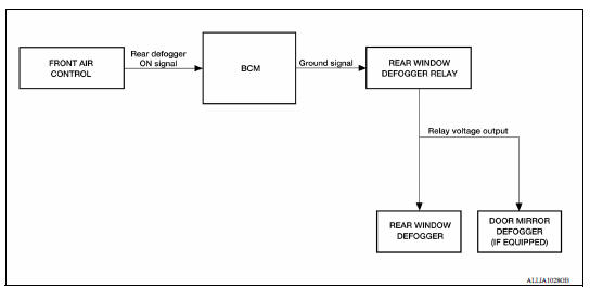
System Description
Operation Description
- When rear window defogger switch is turned ON while ignition switch is ON, the front air control (rear window defogger switch) transmits rear window defogger switch signal to BCM.
- BCM turns rear window defogger relay ON when rear window defogger switch signal is received.
- Rear window defogger and door mirror defogger (with door mirror defogger) are supplied with power and operate when rear window defogger relay turns ON.
- Rear window defogger ON is displayed when front air control receives signals.
Timer function
- BCM turns rear window defogger relay ON for approximately 15 minutes when rear window defogger switch is turned ON while ignition switch is ON. It makes rear window defogger and door mirror defogger (with door mirror defogger) operate.
- Timer is canceled after pressing rear window defogger switch again during timer operation. Then BCM turns rear window defogger relay OFF. The same reaction also occurs during timer operation, if the ignition switch is turned OFF.
INPUT/OUTPUT SIGNAL CHART
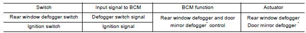
*: With door mirror defogger
DIAGNOSIS SYSTEM (BCM) (WITH INTELLIGENT KEY SYSTEM)
COMMON ITEM
COMMON ITEM : CONSULT Function (BCM - COMMON ITEM)
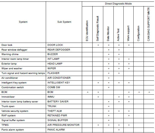
APPLICATION ITEM
CONSULT performs the following functions via CAN communication with BCM.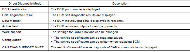
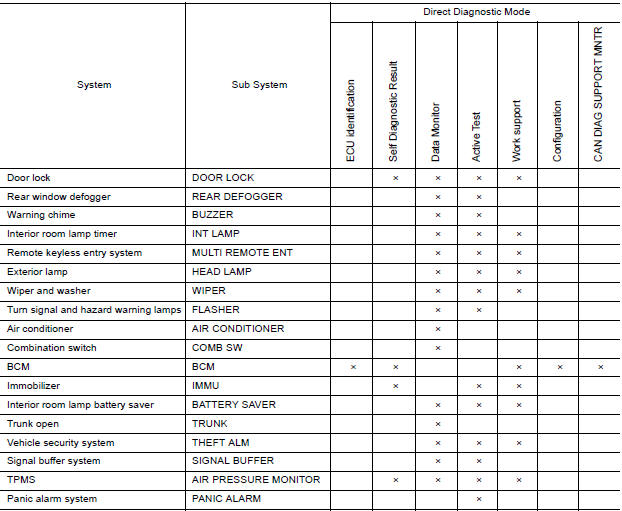
SYSTEM APPLICATION
BCM can perform the following functions.
REAR DEFOGGER
REAR DEFOGGER : CONSULT Function (BCM - REAR DEFOGGER)
DATA MONITOR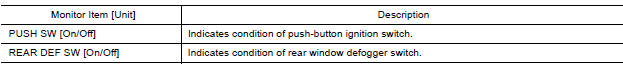
ACTIVE TEST
DIAGNOSIS SYSTEM (BCM) (WITHOUT INTELLIGENT KEY SYSTEM)
COMMON ITEM
COMMON ITEM : CONSULT Function (BCM - COMMON ITEM)
APPLICATION ITEM
CONSULT performs the following functions via CAN communication with BCM.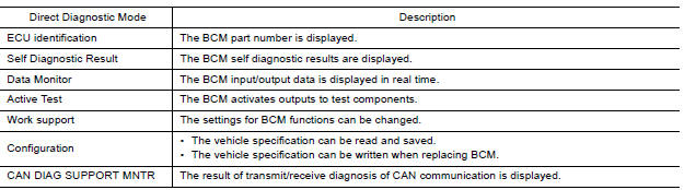
SYSTEM APPLICATION
BCM can perform the following functions.
REAR DEFOGGER
REAR DEFOGGER : CONSULT Function (BCM - REAR DEFOGGER)
DATA MONITOR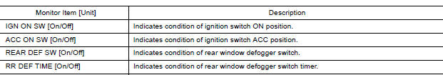
ACTIVE TEST
ECU DIAGNOSIS INFORMATION
BCM
List of ECU Reference
| ECU | Reference |
| BCM (with Intelligent Key system) | BCS "Reference Value" |
| BCS "Fail-safe" | |
| BCS "DTC Inspection Priority Chart" | |
| BCS "DTC Index" | |
| BCM (without Intelligent Key system) | BCS "Reference Value" |
| BCS "Fail-safe" | |
| BCS "DTC Inspection Priority Chart" | |
| BCS"DTC Index" |
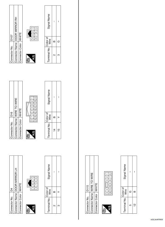
WIRING DIAGRAM
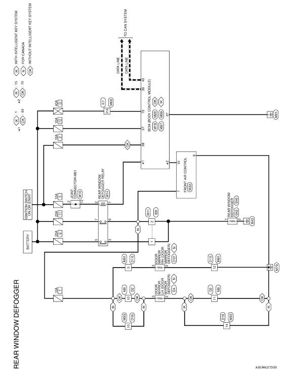
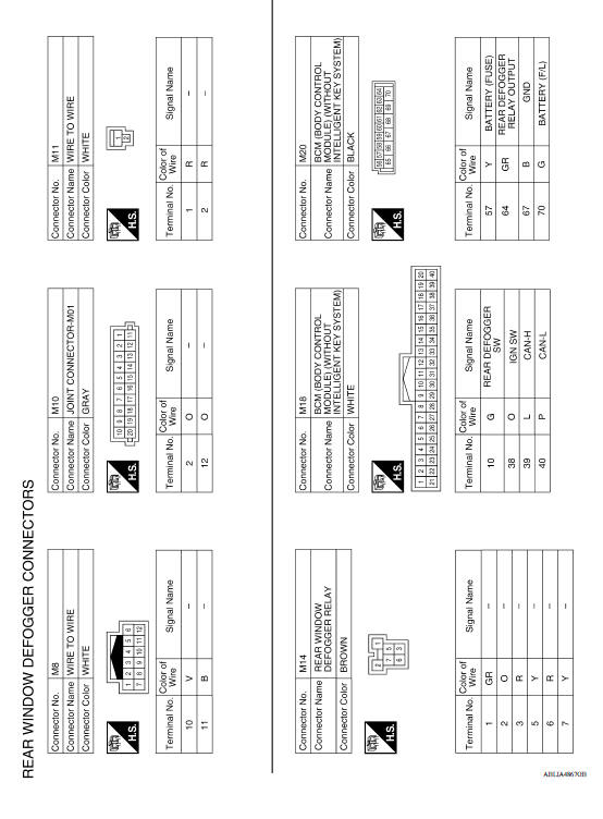
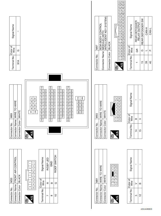
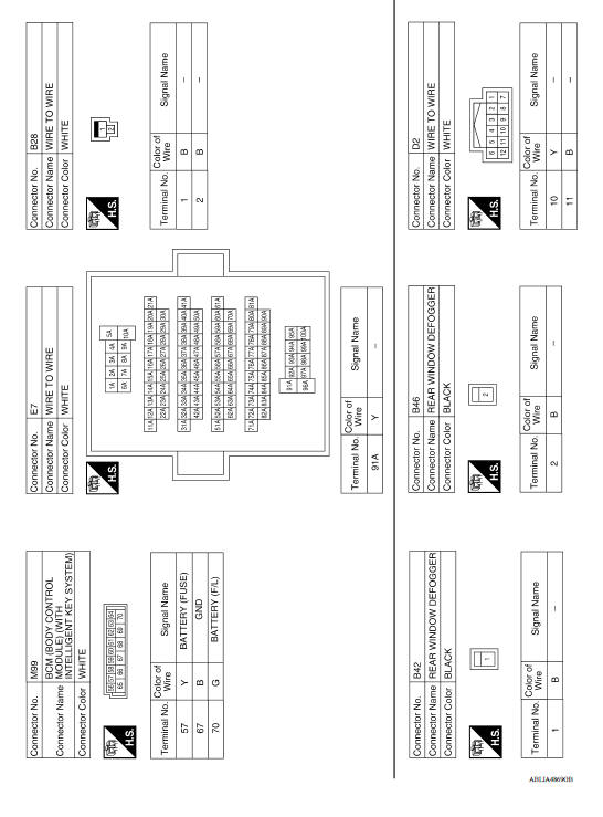
REAR WINDOW DEFOGGER SYSTEM
Wiring Diagram
BASIC INSPECTION
 Precautions
Precaution for Supplemental Restraint System (SRS) "AIR BAG" and "SEAT BELT PRE-TENSIONER" The Supplemental Restraint System such as "AIR BAG" and "SEAT BELT PRE-TENSIONER", us ...
Diagnosis and repair work flow
Work Flow OVERALL SEQUENCE DETAILED FLOW 1. GET INFORMATION FOR SYMPTOM Get the detailed information from the customer about the symptom (the condition and the environment when the incident ...
Other materials:
Child safety
WARNING
Do not allow children to play with the seat
belts. Most seating positions are
equipped with Automatic Locking Retractor
(ALR) mode seat belts. If the seat belt
becomes wrapped around a child's neck
with the ALR mode activated, the child can
be seriously injured or killed if the seat
...
Timing chain
Exploded View
1. Timing chain slack guide 2. Timing chain tensioner 3. Camshaft sprocket
(EXH)
4. Camshaft sprocket (INT) 5. Plug 6. Front oil seal
7. Crankshaft pulley 8. Crankshaft pulley bolt 9. Front cover
10. Crankshaft sprocket 11. Crankshaft sprocket key 12. Oil pump sprocket
13. O ...
Categories
- Manuals Home
- Nissan Versa Owners Manual
- Nissan Versa Service Manual
- Video Guides
- Questions & Answers
- External Resources
- Latest Updates
- Most Popular
- Sitemap
- Search the site
- Privacy Policy
- Contact Us

0.005