Nissan Versa (N17): Timing chain
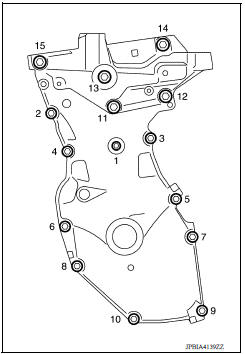
Exploded View
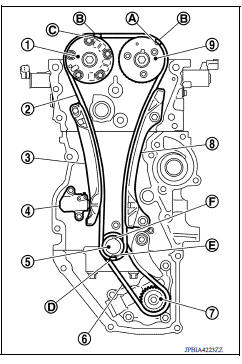
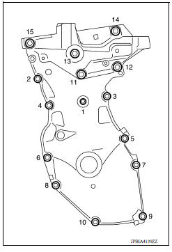
1. Timing chain slack guide 2. Timing chain tensioner 3. Camshaft sprocket (EXH) 4. Camshaft sprocket (INT) 5. Plug 6. Front oil seal 7. Crankshaft pulley 8. Crankshaft pulley bolt 9. Front cover 10. Crankshaft sprocket 11. Crankshaft sprocket key 12. Oil pump sprocket 13. Oil pump drive chain 14. Oil pump drive chain tensioner 15. Timing chain 16. Timing chain tension guide A. Refer to installation procedure.
Removal and Installation
CAUTION:
The rotation direction indicated in the text is as viewed from the engine front.
NOTE:
When removing components such as hoses, tubes/lines, etc., cap or plug openings to prevent fluid from spilling.
REMOVAL
- Remove front wheel and tire (RH) using power tool.
- Remove front fender protector (RH).
- Drain engine oil.
CAUTION:
- Perform this step when engine is cold.
- Do not spill engine oil on drive belt.
- Drain coolant.
- Remove the following parts.
- Intake manifold.
- Drive belt.
- Rocker cover.
- Water pump pulley.
- Support the bottom surface of engine using a transmission jack, and then remove the engine bracket and insulator (RH).
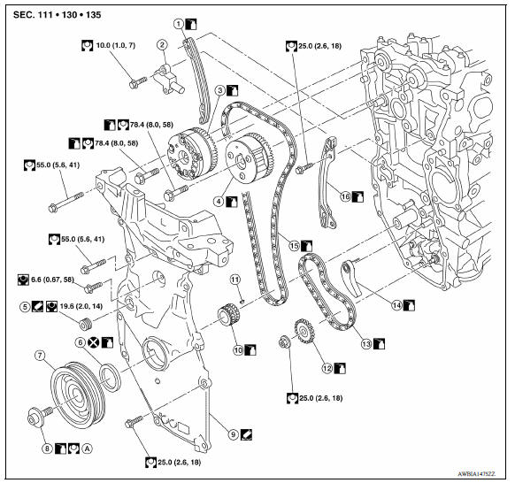
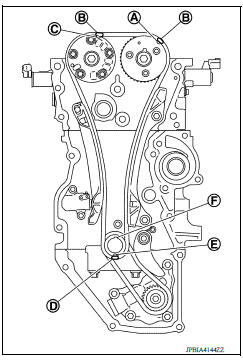
- Set No. 1 cylinder at TDC of its compression stroke:
a. Rotate crankshaft pulley (2) clockwise and align TDC mark (without paint mark) (A) to timing indicator (1) on front cover.
(B) : White paint mark (Not use for service)
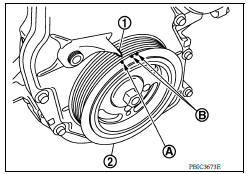
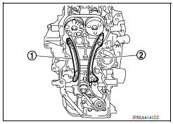
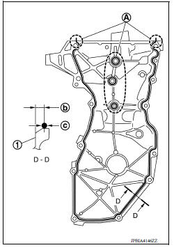
b. Check the matching marks on each camshaft sprocket are positioned as shown.
(1) : Timing chain
(2) : Camshaft sprocket (EXH)
(3) : Camshaft sprocket (INT)
(A) : Matching mark (Peripheral groove)
(B) : Pink link
(C) : Matching mark (Peripheral groove)
- If not, rotate crankshaft pulley one more turn to align matching marks to the positions.
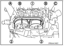
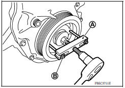
- Remove crankshaft pulley:
a. Secure crankshaft pulley (1) using suitable tool (A).
b. Loosen and pull out crankshaft pulley bolt.
CAUTION:
Do not remove the bolts as they will be used as a supporting point for the pulley puller.
c. Attach Tool (A) in the M 6 thread hole on crankshaft pulley, and remove crankshaft pulley.
(B) : M6 bolt
Tool number : KV11123000 ( - )
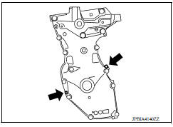
9. Remove front cover:
a. Loosen bolts in the reverse order as shown.
b. Cut liquid gasket by prying the position (
 ) as shown, and then
remove the front cover.
) as shown, and then
remove the front cover.
10. Remove front oil seal from front cover using a suitable tool.
CAUTION:
Be careful not to damage the front cover.
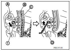
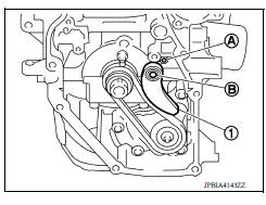
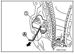
11. Remove chain tensioner (1):
a. Fully push down the chain tensioner lever (A), and then push the plunger (C) into the inside of tensioner.
- The tab (B) is released by fully pushing the lever down. Then the plunger can be moved.
b. Pull up the lever to align its hole position with the body hole position
- When the lever hole is aligned with the body hole position, the plunger is secured.
- When the protrusion parts of the plunger ratchet and the tab face each other, both hole positions are not aligned. At that time, correctly engage them and align these hole positions by slightly moving the plunger.
c. Insert the stopper pin (D) into the body hole through the lever hole, and then secure the lever at the upper position.
NOTE:
A hexagonal wrench of 2.5 mm (0.098 in) is used as a stopper pin (D).
d. Remove chain tensioner.
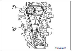
12. Remove the timing chain tension guide (2) and the timing chain slack guide (1).
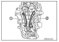
13. Remove the timing chain (2).
- Pull the timing chain slack toward the camshaft sprocket (EXH) (1), and then remove the timing chain and start the removal from camshaft sprocket (EXH) side.
CAUTION:
Do not rotate crankshaft or camshaft while timing chain is removed. It causes interference between valve and piston.
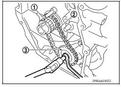
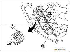
14. Remove the crankshaft sprocket and the oil pump drive related parts:
a. Remove oil pump drive chain tensioner (1).
- Pull out from the shaft (B) and spring attaching holes (A).
b. Hold the top of the oil pump shaft using the socket (size: E8), and then loosen the oil pump sprocket nut and remove it.
c. Remove the crankshaft sprocket (1), the oil pump drive chain (2), and the oil pump sprocket (3) at the same time.
INSTALLATION
NOTE:
For installation follow the relationship between the matching mark on each timing chain and that of the corresponding sprocket, with the components installed.
(1) : Camshaft sprocket (EXH)
(2) : Timing chain
(3) : Timing chain slack guide
(4) : Chain tensioner
(5) : Crankshaft sprocket
(6) : Oil pump drive chain
(7) : Oil pump sprocket
(8) : Timing chain tension guide
(9) : Camshaft sprocket (INT)
(A) : Matching mark (Peripheral groove)
(B) : Pink link
(C) : Matching mark (Peripheral groove)
(D) : Orange link
(E) : Matching mark (stamp)
(F) : Crankshaft key (point straight up)
1. Install the crankshaft sprocket and the oil pump drive related parts:
a. Install the crankshaft sprocket (1), the oil pump drive chain (2), and the oil pump sprocket (3) at the same time.
 : Engine front
- Install the crankshaft sprocket so that its invalid gear area (A) is toward the back of the engine.
- Install the oil pump sprocket so that its protrusion faces the front of engine.
NOTE:
There is no matching mark in the oil pump drive related parts.
b. Hold the top of the oil pump shaft using the socket (size: E8), and then tighten the oil pump sprocket nut.
(1) : Crankshaft sprocket
(2) : Oil pump drive chain
(3) : Oil pump sprocket
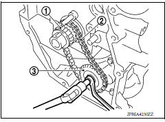
c. Install oil pump drive chain tensioner (1).
- Insert the body into the shaft (B) while inserting the spring into the attaching hole (A) of cylinder block front surface.
- Check that the tension is applied to the oil pump drive chain after installing.
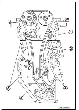
2. Install timing chain:
(A) : Matching mark (Peripheral groove)
(B) : Pink link
(C) : Matching mark (Peripheral groove)
(D) : Orange link
(E) : Matching mark (stamp)
(F) : Crankshaft key (point straight up)
- Install by aligning matching marks on each sprocket and timing chain.
- If these matching marks are not aligned, rotate the camshaft slightly to correct the position.
CAUTION:
- After the matching marks are aligned, keep them aligned by holding them.
- To avoid skipped teeth, do not rotate crankshaft and camshaft until front cover is installed.
3. Install timing chain tension guide (2) and timing chain slack guide (1).
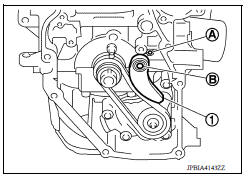
4. Install chain tensioner (1).
- Secure the plunger at the most compressed position using a stopper pin (A), and then install it.
- Pull out the stopper pin after installing the chain tensioner.
- Check matching mark position of timing chain and each sprocket again.
- Install the front oil seal to the front cover.
- Install front cover with the following procedure:
a. Apply a continuous bead of liquid gasket to the front cover as shown.
Use Genuine Silicone RTV Sealant or equivalent.
(1) : Cylinder head
(2) : Cylinder block
(3) : Oil pan (upper)
(A) : Liquid gasket application area [3.0 4.0 mm (0.12 0.16 in) diameter]
Tool number : WS39930000
b. Apply a continuous bead of liquid gasket to front cover as shown.
Use Genuine Silicone RTV Sealant or equivalent.
(1) : Front cover edge
(A) : Liquid gasket application area
(b) : 4.0 5.6 mm
(c) : Liquid gasket application area [3.0 4.0 mm (0.12 0.16 in) diameter]
c. Tighten bolts in the numerical order as shown.
d. After all bolts are tightened, retighten them to specified torque in numerical order as shown.
CAUTION:
Be sure to wipe off any excessive liquid gasket leaking to surface.
8. Insert crankshaft pulley by aligning with crankshaft key.
- When inserting crankshaft pulley with a plastic hammer, tap on its center portion (not circumference).
CAUTION:
Do not damage front oil seal lip section.
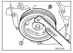
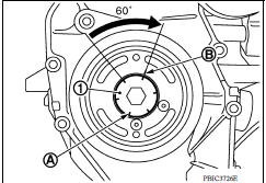
9. Tighten crankshaft pulley bolt:
- Secure crankshaft pulley with a suitable tool and tighten crankshaft pulley bolt.
a. Apply new engine oil to thread and seat surfaces of crankshaft pulley bolt.
b. Tighten crankshaft pulley bolt.
Crankshaft pulley bolt : 35.0 N*m (3.6 kgm, 26 ftlb)
c. Put a paint mark (B) on crankshaft pulley, mating with any one of six easy to recognize angle marks (A) on crankshaft bolt flange (1).
d. Turn another 60 degrees clockwise (angle tightening).
- Check the tightening angle with movement of one angle mark.
10. Check that crankshaft turns smoothly by rotating by hand clockwise.
11. Installation of the remaining components is in the reverse order of removal.
INSPECTION AFTER INSTALLATION
- Before starting engine, check oil/fluid levels, including engine coolant and engine oil. If less than required quantity, fill to the specified level.
- Use procedure below to check for fuel leakage.
- Turn ignition switch ON (with engine stopped). With fuel pressure applied to fuel piping, check for fuel leakage at connection points.
- Start engine. With engine speed increased, check again for fuel leakage at connection points.
- Run engine to check for unusual noise and vibration.
NOTE:
If hydraulic pressure inside timing chain tensioner drops after removal and installation, slack in the guide may generate a pounding noise during and just after engine start. However, this is normal. Noise will stop after hydraulic pressure rises.
- Warm up engine thoroughly to make sure there is no leakage of fuel, exhaust gas, or any oils/fluids including engine oil and engine coolant.
- Bleed air from passages in lines and hoses, such as in cooling system.
- After cooling down engine, again check oil/fluid levels including engine oil and engine coolant. Refill to specified level, if necessary.
- Summary of the inspection items:
| Item | Before starting engine | Engine running | After engine stopped | |
| Engine coolant | Level | Leakage | Level | |
| Engine oil | Level | Leakage | Level | |
| Transmission/ transaxle fluid | A/T and CVT Models | Leakage | Level/Leakage | Leakage |
| M/T Models | Level/Leakage | Leakage | Level/Leakage | |
| Other oils and fluids* | Level | Leakage | Level | |
| Fuel | Leakage | Leakage | Leakage | |
| Exhaust gas | Leakage | |||
*Power steering fluid, brake fluid, etc.
 Ignition coil, spark plug and rocker cover
Exploded View 1. Ignition coil 2. Spark plug 3. Rocker cover 4. Hose cramp 5. PCV hose 6. PCV valve 7. Oring 8. Gasket 9. Oil filler cap 10. Oring 11. Intake camshaft position sensor 12. Exhau ...
Camshaft
Exploded View 1. Camshaft bracket (No. 2 to 5) 2. Camshaft bracket (No. 1) 3. Camshaft sprocket (EXH) 4. Exhaust valve timing control solenoid valve 5. Oring 6. Camshaft sprocket (INT) 7. Plug ...
Other materials:
Unbalance steering wheel turning force (torque variation)
Description
Unbalance steering wheel turning force (torque variation).
Diagnosis Procedure
1.PERFORM SELF-DIAGNOSIS
With CONSULT
Turn the ignition switch OFF to ON.
Perform "EPS" self-diagnosis.
Is any DTC detected?
YES >> Check the DTC. Refer to STC "DTC Index".
NO & ...
Roof side molding
Exploded View
1. Roof side molding 2. Roof side molding clip 3. Roof panel
4. Body side outer panel
Removal and Installation
REMOVAL
1. Release roof side molding clip using a suitable tool (A).
: Clip
CAUTION:
Apply protective tape (B) on body to protect the painted
surface from damag ...
Categories
- Manuals Home
- Nissan Versa Owners Manual
- Nissan Versa Service Manual
- Video Guides
- Questions & Answers
- External Resources
- Latest Updates
- Most Popular
- Sitemap
- Search the site
- Privacy Policy
- Contact Us

0.0053