Nissan Versa (N17): Transmission assembly
Exploded View
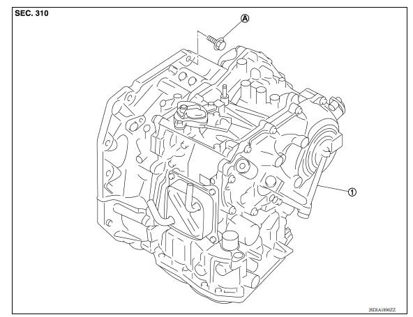
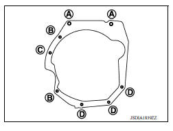
1. Transaxle assembly A : For the tightening torque, refer to TM "Removal and Installation".
Removal and Installation
WARNING:
- Do not open the radiator cap or drain plug when the engine is hot. Hot liquid may spray out, causing serious injury.
- Perform these steps after the coolant temperature has cooled sufficiently.
NOTE:
- When replacing the TCM and transaxle assembly as a set, replace the transaxle assembly first and then replace the TCM. Refer to TM "Description".
- When removing components such as hoses, tubes/lines, etc., cap or plug openings to prevent fluid from spilling.
REMOVAL
- Remove the battery. Refer to PG "Removal and Installation".
- Remove the TCM. Refer to TM "Removal and Installation".
- Remove the battery plate.
- Remove the air duct and air cleaner case. Refer to EM "Removal and Installation".
- Disconnect the harness connectors from the following components and remove the harness from the transaxle.
- CVT unit. Refer to TM "Removal and Installation Procedure for CVT Unit Connector".
- Transmission range switch
- Primary speed sensor
- Secondary speed sensor
- Output speed sensor
- Crankshaft position sensor. Refer to EM "Exploded View".
- Ground
- Disconnect the control cable from the transaxle assembly. Refer to TM "Exploded View".
- Disconnect the CVT water hose A and water hose C from engine side. TM "Removal and Installation".
- Disconnect the heater hose from the water bypass pipe.
- Remove the left and right drive shafts. Refer to FAX "Removal and Installation".
- Remove the drive shaft heat insulator.
- Remove starter motor. Refer to STR "Removal and Installation".
- Remove the right and left fender protectors. Refer to EXT "Removal and Installation".
- Rotate the crankshaft and remove the nuts that secure the drive plate to
the torque converter.
CAUTION: Rotate crankshaft clockwise (as viewed from the front of the engine).
- Remove the rear torque rod. Refer to EM "Exploded View".
- Set a transmission jack under the transaxle assembly.
CAUTION: Be careful not to contact the drain plug when setting the transmission jack.
- Set a transmission jack under the engine assembly.
CAUTION: Be careful not to contact the drain plug when setting the transmission jack.
- Remove the left engine mounting insulator. Refer to EM "Exploded View".
- Remove the left engine mounting bracket (LH). Refer to EM "Exploded View".
- Remove the bolts that fasten the transaxle assembly and engine assembly.
- Remove the transaxle assembly from the vehicle.
CAUTION: Do not drop the torque converter.
INSTALLATION
Installation is in the reverse order of removal.
CAUTION:
- Do not reuse O-rings.
- Apply Genuine NISSAN CVT Fluid NS-3 to the O-rings.
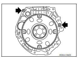
- When installing the transaxle assembly onto the engine assembly,
check the engagement of the dowel pins (
 ).
).
- When using suitable tool (A) for alignment, install it to the alignment stud bolt used to align the torque converter to the drive plate.
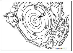
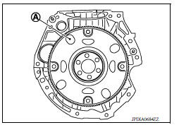
- Rotate the crankshaft so that the alignment hole (A) of drive plate aligns with the position of the torque converter alignment stud bolt.
CAUTION:
- Rotate the crankshaft clockwise (as viewed from the front of the engine).
- Be careful that torque converter stud bolts are aligned to the drive plate holes. Otherwise the stud bolts contact the drive plate.
- Insert the alignment stud bolt of torque converter into the alignment hole of the drive plate, aligning the drive plate holes with the torque converter stud bolts.
CAUTION: Be careful not to strike the drive plate with the torque converter stud bolts.
- When installing the torque converter nuts, temporarily tighten the nuts. Then, after installing the engine and transaxle assembly bolts tighten the nuts to the specified torque.
Tightening torque : 51 N*m (5.2 kg-m, 38 ft-lb)
CAUTION:
- Rotate the crankshaft clockwise (as viewed from the front of the engine).
- Check the tightening torque for the crankshaft pulley bolts after the bolts fastening the drive plate and torque converter have been tightened and the crankshaft pulley bolts have been secured.
Refer to EM "Removal and Installation".
- Install the transaxle assembly and engine assembly bolts according to the following standards.
Inspection and Adjustment
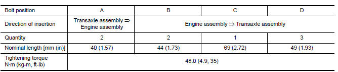
INSPECTION BEFORE INSTAL
Check the distance (A) between the converter housing and torque converter.
B : Scale
C : Straightedge
Dimension (A) : TM-457, "Torque Converter"
INSPECTION AFTER INSTALLATION
Check the following items:
- For CVT position, refer to TM "Inspection and Adjustment".
- Before starting engine, check oil/fluid levels including engine coolant and engine oil. If less than required quantity, fill to the specified level. Refer to MA "Fluids and Lubricants".
- Use procedure below to check for fuel leakage.
- Turn ignition switch ON (with engine stopped). With fuel pressure applied to fuel piping, check for fuel leakage at connection points.
- Start engine. With engine speed increased, check again for fuel leakage at connection points.
- Run engine to check for unusual noise and vibration.
NOTE: If hydraulic pressure inside timing chain tensioner drops after removal and installation, slack in the guide may generate a pounding noise during and just after engine start. However, this is normal. Noise will stop after hydraulic pressure rises.
- Warm up engine thoroughly to make sure there is no leakage of fuel, exhaust gas, or any oils/fluids including engine oil and engine coolant.
- Bleed air from passages in lines and hoses, such as in cooling system.
- After cooling down engine, again check oil/fluid levels including engine oil and engine coolant. Refill to specified level, if necessary.
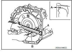
- Summary of the inspection items:
*Power steering fluid, brake fluid, etc.
ADJUSTMENT AFTER INSTALLATION
- Adjust the CVT fluid level. TM "Adjustment".
- Perform "ADDITIONAL SERVICE WHEN REPLACING TRANSAXLE ASSEMBLY". Refer to TM"Description".
 PLUG
PLUG
Description Replace the O-ring if oil leakage or exudes from the plug. Exploded View 1. Plug 2. O-ring 3. O-ring 4. Plug Genuine NISSAN CVT Fluid NS-3 Removal and Installation REMOVAL ...
Service data and specifications
(SDS)
General Specification CAUTION: Use only Genuine NISSAN CVT Fluid NS-3. Do not mix with other fluid. Use only Genuine NISSAN CVT Fluid NS-3. Using transmission fluid other than Genui ...
Other materials:
NISSAN Intelligent Key (if so equipped)
WARNING
Radio waves could adversely affect
electric medical equipment. Those who
use a pacemaker should contact the
electric medical equipment manufacturer
for the possible influences before
use.
The Intelligent Key transmits radio
waves when the buttons are pressed.
The FAA ad ...
Parking/parking on hills
WARNING
Do not stop or park the vehicle over
flammable materials such as dry grass,
waste paper or rags. They may ignite
and cause a fire.
Safe parking procedures require that
both the parking brake be set and the
transmission placed into P (Park) or in
an appropriate gear for ...
Categories
- Manuals Home
- Nissan Versa Owners Manual
- Nissan Versa Service Manual
- Video Guides
- Questions & Answers
- External Resources
- Latest Updates
- Most Popular
- Sitemap
- Search the site
- Privacy Policy
- Contact Us

0.0054