Nissan Versa (N17): Inside key antenna
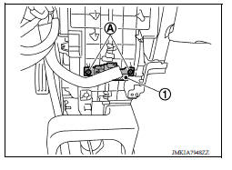
Instrument center
INSTRUMENT CENTER : Removal and Installation
REMOVAL
1. Remove the instrument lower center panel. Refer to IP "Removal and Installation".
2. Remove screws (A) and the inside key antenna (instrument center) (1).
INSTALLATION
Installation is in the reverse order of removal.
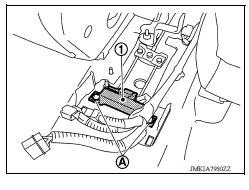
Console
CONSOLE : Removal and Installation
REMOVAL
1. Remove the center console assembly. Refer to IP "Removal and Installation".
2. Remove clips (A) and the inside key antenna (console) (1).
INSTALLATION
Installation is in the reverse order of removal.
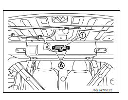
Trunk room
TRUNK ROOM : Removal and Installation
REMOVAL
Remove clips (A) and the inside key antenna (trunk room) (1).
INSTALLATION
Installation is in the reverse order of removal.
 Door switch
Exploded View 1. Door switch 2. Door switch bolt Removal and Installation REMOVAL 1. Remove the door switch bolt (A). 2. Disconnect the harness connector and remove door switch (1). INST ...

Other materials:
Compressor
Exploded View
1. Compressor
Removal and Installation
CAUTION:
Perform oil return operation before each refrigeration system disassembly.
However, if a large amount
of refrigerant or oil is detected, do not perform oil return operation. Refer to
HA "Perform Oil
Return Operation&q ...
Steering column covers
Removal and Installation
REMOVAL
Remove instrument lower panel LH. Refer to IP "Removal and
Installation".
Remove lower knee protector (LH) bolts and lower knee protector (LH).
Refer to IP "Exploded View".
Remove steering column covers.
a. Remove steering colu ...
Categories
- Manuals Home
- Nissan Versa Owners Manual
- Nissan Versa Service Manual
- Video Guides
- Questions & Answers
- External Resources
- Latest Updates
- Most Popular
- Sitemap
- Search the site
- Privacy Policy
- Contact Us

0.0053