Nissan Versa (N17): U1000 CAN Comm
Description
Refer to LAN "CAN COMMUNICATION SYSTEM : System Description".
DTC Logic
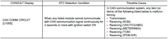
DTC DETECTION LOGIC
NOTE:
U1000 can be set if a module harness was disconnected and reconnected, perhaps
during a repair. Confirm
that there are actual CAN diagnostic symptoms and a present DTC by performing
the Self Diagnostic Result
procedure.
Diagnosis Procedure
1. PERFORM SELF DIAGNOSTIC RESULT
1. Turn ignition switch ON and wait for 2 second or more.
2. Check "SELF- DIAG RESULTS".
Is "CAN COMM CIRCUIT" displayed?
YES >> Perform CAN Diagnosis as described in DIAGNOSIS section of CONSULT Operation Manual.
NO >> Refer to GI "Intermittent Incident".
 Inspection and adjustment
U1010 Control unit (CAN)
DTC Logic DTC DETECTION LOGIC Diagnosis Procedure 1.REPLACE BCM When DTC "U1010 ...
Other materials:
Battery
Keep the battery surface clean and dry.
Clean the battery with a solution of baking
soda and water.
Make certain the terminal connections are
clean and securely tightened.
If the vehicle is not to be used for 30 days or
longer, disconnect the negative (-) battery
terminal cable to ...
P0983 Shift solenoid D
DTC Logic
DTC DETECTION LOGIC
DTC
Trouble diagnosis name
DTC detection condition
Possible causes
P0983
Shift Solenoid D Control Circuit
High
The following diagnosis conditions
are met, and the current
monitor reading of the TCM line
pressure solenoid val ...
Categories
- Manuals Home
- Nissan Versa Owners Manual
- Nissan Versa Service Manual
- Video Guides
- Questions & Answers
- External Resources
- Latest Updates
- Most Popular
- Sitemap
- Search the site
- Privacy Policy
- Contact Us

0.0056