Nissan Versa (N17): U1002 System comm (CAN)
DTC Logic
DTC DETECTION LOGIC 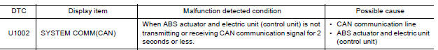
DTC CONFIRMATION PROCEDURE
1.PRECONDITIONING
If "DTC CONFIRMATION PROCEDURE" has been previously conducted, always turn ignition switch OFF and wait at least 10 seconds before conducting the next test.
>> GO TO 2.
2.DTC REPRODUCTION PROCEDURE
With CONSULT
- Turn the ignition switch ON.
- Perform self diagnosis for "ABS".
Is DTC "U1002" detected?
YES >> Proceed to BRC"Diagnosis Procedure".
NO >> Inspection End.
Diagnosis Procedure
CAUTION:
- Never apply 7.0 V or more to the measurement terminal.
- Use a tester with open terminal voltage of 7.0 V or less.
- Turn the ignition switch OFF and disconnect the battery cable from the negative terminal when checking the harness.
1.CHECK CAN DIAGNOSIS SUPPORT MONITOR
- Select "ABS" and "CAN Diagnosis Support Monitor" in order with CONSULT.
- Check malfunction history between each control unit connected to ABS actuator and electric unit (control unit).
Check the result of "PAST"?
All items are "OK">>Refer to GI "Intermittent Incident".
"TRANSMIT DIAG" is other than "OK">>GO TO 2.
A control unit other than ABS actuator and electric unit (control unit) is anything other than "OK">>GO TO 3.
2.CHECK TRANSMITTING SIDE UNIT
Check the ABS actuator and electric unit (control unit) harness connector terminals 14 and 26 for damage or loose connection.
Is the inspection result normal?
YES >> Erase self-diagnosis results. Then perform self-diagnosis for "ABS" with CONSULT.
NO >> Recheck terminals for damage or loose connection.
3.CHECK APPLICABLE CONTROL UNIT
Check damage or loose connection of each CAN communication line harness connector terminals.
Is the inspection result normal?
YES >> Erase self-diagnosis results. Then perform self-diagnosis for applicable control unit with CONSULT.
NO >> Recheck terminals for damage or loose connection.
 U1000 CAN Comm circuit
DTC Logic DTC DETECTION LOGIC Diagnosis Procedure 1.CHECK DTC DETECTION With CONSULT. Turn ignition switch ON. Perform self diagnostic result. Is DTC U1000 detected? YES >> Proce ...
Parking brake switch
Component Function Check 1.CHECK PARKING BRAKE SWITCH OPERATION Check that brake warning lamp in combination meter turns ON/OFF when parking brake is actuated. Is the inspection result normal? ...
Other materials:
4-speed automatic transmission fluid (ATF) (if so equipped)
When checking or replacement of automatic
transmission fluid is required, it is recommended
that you visit a NISSAN dealer for servicing.
WARNING
When the engine is running, keep
hands, jewelry and clothing away from
any moving parts such as the cooling
fan and drive belts
Automatic t ...
Ignition coil, spark plug and rocker cover
Exploded View
1. Ignition coil 2. Spark plug 3. Rocker cover
4. Hose cramp 5. PCV hose 6. PCV valve
7. Oring 8. Gasket 9. Oil filler cap
10. Oring 11. Intake camshaft position sensor 12. Exhaust camshaft position
sensor
13. Clip A. To intake manifold
Removal and Installation
REMOVAL
...
Categories
- Manuals Home
- Nissan Versa Owners Manual
- Nissan Versa Service Manual
- Video Guides
- Questions & Answers
- External Resources
- Latest Updates
- Most Popular
- Sitemap
- Search the site
- Privacy Policy
- Contact Us

0.006