Nissan Versa (N17): VDC/TCS/ABS
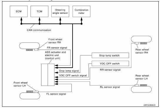
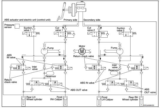
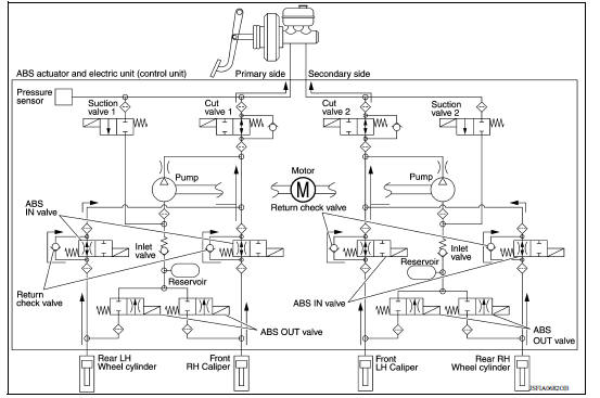
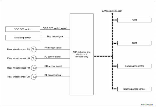
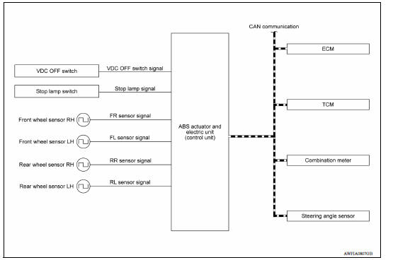
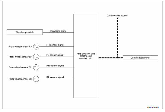
VDC/TCS/ABS : System Diagram
VDC/TCS/ABS : System Description
- The system switches fluid pressure of each brake caliper and each wheel cylinder to increase, to hold, or to decrease according to signals from control unit in ABS actuator and electric unit (control unit). This control system is applied to VDC, TCS, ABS and EBD functions.
- Fail-safe function is available for each function and is activated by each function when system malfunction occurs.
INPUT SIGNAL AND OUTPUT SIGNAL
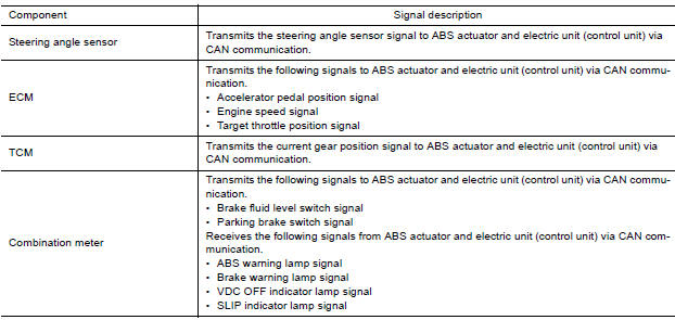
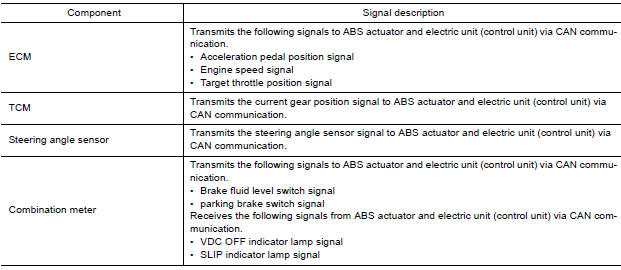
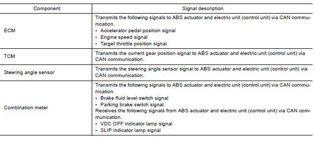
Major signal transmission between each unit via communication lines is shown in the following table.
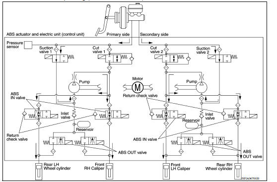
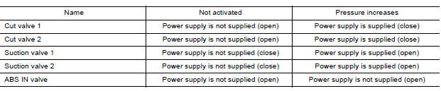
VALVE OPERATION (VDC AND TCS FUNCTIONS)
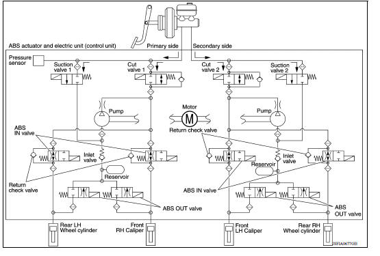
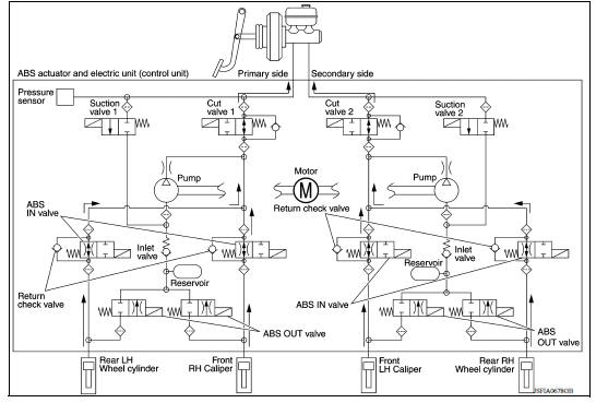
The control unit built in the ABS actuator and electric unit (control unit) controls fluid pressure of the brake calipers by operating each valve.
VDC and TCS Functions are Operating (Pressure Increases)
Front RH brake caliper
- Brake fluid is conveyed to the pump from the master cylinder through suction valve 1 and is pressurized by the pump operation. The pressurized brake fluid is supplied to the front RH brake caliper through the ABS IN valve. For the left caliper, brake fluid pressure is maintained because the pressurization is unnecessary. The pressurization for the left caliper is controlled separately from the right caliper.
Front LH brake caliper
- Brake fluid is conveyed to the pump from the master cylinder through suction valve 2 and is pressurized by the pump operation. The pressurized brake fluid is supplied to the front LH brake caliper through the ABS IN valve. For the right caliper, brake fluid pressure is maintained because the pressurization is unnecessary.
The pressurization for the right caliper is controlled separately from the left caliper.
Rear RH wheel cylinder
- Brake fluid is conveyed to the pump from the master cylinder through suction valve 2 and is pressurized by the pump operation. The pressurized brake fluid is supplied to the rear RH wheel cylinder through the ABS IN valve. For the left wheel cylinder, brake fluid pressure is maintained because the pressurization is unnecessary.
The pressurization for the left wheel cylinder is controlled separately from the right wheel cylinder.
Rear LH wheel cylinder
- Brake fluid is conveyed to the pump from the master cylinder through suction valve 1 and is pressurized by the pump operation. The pressurized brake fluid is supplied to the rear LH wheel cylinder through the ABS IN valve. For the right wheel cylinder, brake fluid pressure is maintained because the pressurization is unnecessary. The pressurization for the right wheel cylinder is controlled separately from the left wheel cylinder.
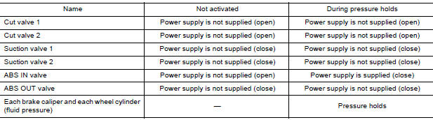
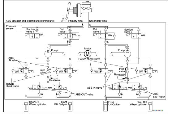
VDC and TCS Functions Start Operating (Pressure Holds)
VDC and TCS Functions Start Operating (Pressure Holds)
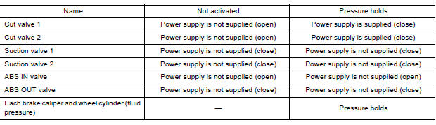
Front RH brake caliper
- Since the cut valve 1 and the suction valve 1 are closed, the front RH brake caliper, master cylinder, and reservoir are blocked. This maintains fluid pressure applied on the front RH brake caliper. The pressurization for the left caliper is controlled separately from the right caliper.
Front LH brake caliper
- Since the cut valve 2 and the suction valve 2 are closed, the front LH brake caliper, master cylinder, and reservoir are blocked. This maintains fluid pressure applied on the front LH brake caliper. The pressurization for the right caliper is controlled separately from the left caliper.
Rear RH wheel cylinder
- Since the cut valve 2 and the suction valve 2 are closed, the rear RH wheel cylinder, master cylinder, and reservoir are blocked. This maintains fluid pressure applied on the rear RH wheel cylinder. The pressurization for the left wheel cylinder is controlled separately from the right wheel cylinder.
Rear LH wheel cylinder
- Since the cut valve 1 and the suction valve 1 are closed, the rear LH wheel cylinder, master cylinder, and reservoir are blocked. This maintains fluid pressure applied on the rear LH wheel cylinder. The pressurization for the right wheel cylinder is controlled separately from the left wheel cylinder.
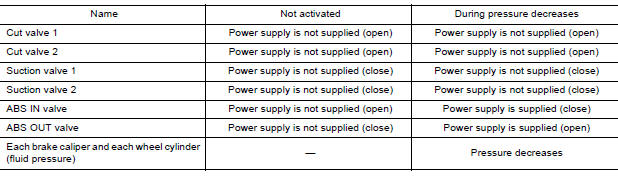
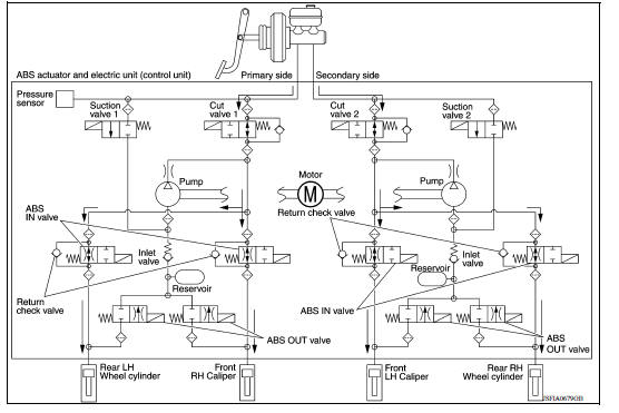
VDC and TCS Functions Operating (Pressure Decreases)
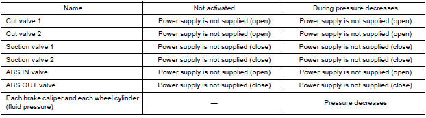
Front RH brake caliper
- Since the suction valve 1 and the ABS OUT valve are closed and the cut valve 1 and the ABS IN valve are open, the fluid pressure applied on the front RH brake caliper is reduced by supplying the fluid pressure to the master cylinder via the ABS IN valve and the cut valve 1. The pressurization for the right caliper is controlled separately from the left caliper.
Front LH brake caliper
- Since the suction valve 2 and the ABS OUT valve are closed and the cut valve 2 and the ABS IN valve are open, the fluid pressure applied on the front LH brake caliper is reduced by supplying the fluid pressure to the master cylinder via the ABS IN valve and the cut valve 2. The pressurization for the left caliper is controlled separately from the right caliper.
Rear RH wheel cylinder
- Since the suction valve 2 and the ABS OUT valve are closed and the cut valve 2 and the ABS IN valve are open, the fluid pressure applied on the rear RH wheel cylinder is reduced by supplying the fluid pressure to the master cylinder via the ABS IN valve and the cut valve 2. The pressurization for the right wheel cylinder is controlled separately from the left wheel cylinder.
Rear LH wheel cylinder
- Since the suction valve 1 and the ABS OUT valve are closed and the cut valve 1 and the ABS IN valve are open, the fluid pressure applied on the rear LH wheel cylinder is reduced by supplying the fluid pressure to the master cylinder via the ABS IN valve and the cut valve 1. The pressurization for the left wheel cylinder is controlled separately from the right wheel cylinder.
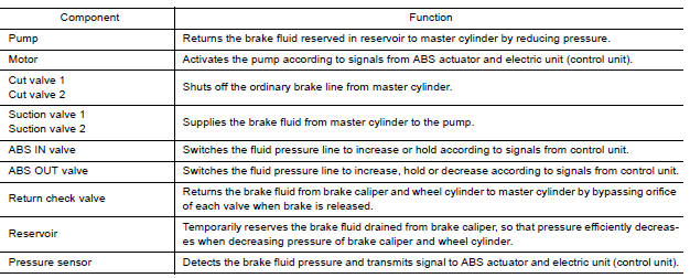
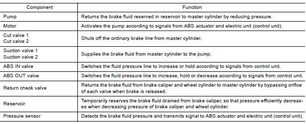
Component Parts and Function
VALVE OPERATION (ABS AND EBD FUNCTIONS)
The control unit built into the ABS actuator and electric unit (control unit) controls fluid pressure of the brake calipers by operating each valve.
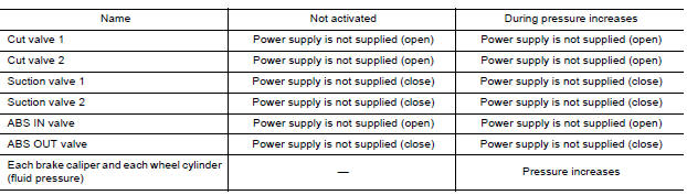
Brake Pedal Applied or ABS Function Operating (Pressure Increases)

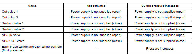
Front RH brake caliper
- When the cut valve 1 and the ABS IN valve opens, brake fluid is supplied to the front RH brake caliper from the master cylinder through the ABS IN valve. Brake fluid does not flow into the reservoir because the ABS OUT valve is closed.
Front LH brake caliper
- When the cut valve 2 and the ABS IN valve opens, brake fluid is supplied to the front LH brake caliper from the master cylinder through the ABS IN valve. Brake fluid does not flow into the reservoir because the ABS OUT valve is closed.
Rear RH wheel cylinder
- When the cut valve 2 and the ABS IN valve opens, brake fluid is supplied to the rear RH wheel cylinder from the master cylinder through the ABS IN valve. Brake fluid does not flow into the reservoir because the ABS OUT valve is closed.
Rear LH wheel cylinder
- When the cut valve 1 and the ABS IN valve opens, brake fluid is supplied to the rear LH wheel cylinder from the master cylinder through the ABS IN valve. Brake fluid does not flow into the reservoir because the ABS OUT valve is closed.
ABS Function Starts Operating (Pressure Holds)
Front RH brake caliper
- Since the ABS IN valve and the ABS OUT valve are closed, the front RH brake caliper, master cylinder, and reservoir are blocked. This maintains fluid pressure applied on the front RH brake caliper.
Front LH brake caliper
- Since the ABS IN valve and the ABS OUT valve are closed, the front LH brake caliper, master cylinder, and reservoir are blocked. This maintains fluid pressure applied on the front LH brake caliper.
Rear RH wheel cylinder
- Since the ABS IN valve and the ABS OUT valve are closed, the rear RH wheel cylinder, master cylinder, and reservoir are blocked. This maintains fluid pressure applied on the rear RH wheel cylinder.
Rear LH wheel cylinder
- Since the ABS IN valve and the ABS OUT valve are closed, the rear LH wheel cylinder, master cylinder, and reservoir are blocked. This maintains fluid pressure applied on the rear LH wheel cylinder.
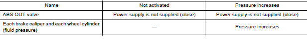
ABS Function Operating (Pressure Decreases)
Front RH brake caliper
- Since the ABS IN valve is closed and the ABS OUT valve is opened, fluid pressure applied on the front RH brake caliper is supplied to the reservoir through the ABS OUT valve. This fluid pressure decreases when sent to the master cylinder by the pump.
Front LH brake caliper
- Since the ABS IN valve is closed and the ABS OUT valve is opened, fluid pressure applied on the front LH brake caliper is supplied to the reservoir through the ABS OUT valve. This fluid pressure decreases when sent to the master cylinder by the pump.
Rear RH wheel cylinder
- Since the ABS IN valve is closed and the ABS OUT valve is opened, fluid pressure applied on the rear RH wheel cylinder is supplied to the reservoir through the ABS OUT valve. This fluid pressure decreases when sent to the master cylinder by the pump.
Rear LH wheel cylinder
- Since the ABS IN valve is closed and the ABS OUT valve is opened, fluid pressure applied on the rear LH wheel cylinder is supplied to the reservoir through the ABS OUT valve. This fluid pressure decreases when sent to the master cylinder by the pump.
ABS Function Operating (Pressure Increases)
Front RH brake caliper
- Brake fluid is supplied to the front RH brake caliper from the master cylinder through the cut valve 1 and the ABS IN valve. Since the suction valve 1 and the ABS OUT valve is closed, the fluid does not flow into the reservoir. The amount of brake fluid supplied to the front RH brake caliper from the master cylinder is controlled according to time that the ABS IN valve is not energized (time that the ABS IN valve is open).
Front LH brake caliper
- Brake fluid is supplied to the front LH brake caliper from the master cylinder through the cut valve 2 and the ABS IN valve. Since the suction valve 2 and the ABS OUT valve is closed, the fluid does not flow into the reservoir. The amount of brake fluid supplied to the front LH brake caliper from the master cylinder is controlled according to time that the ABS IN valve is not energized (time that the ABS IN valve is open).
Rear RH wheel cylinder
- Brake fluid is supplied to the rear RH wheel cylinder from the master cylinder through the cut valve 2 and the ABS IN valve. Since the suction valve 2 and the ABS OUT valve is closed, the fluid does not flow into the reservoir. The amount of brake fluid supplied to the rear RH wheel cylinder from the master cylinder is controlled according to time that the ABS IN valve is not energized (time that the ABS IN valve is open).
Rear LH wheel cylinder
- Brake fluid is supplied to the rear LH wheel cylinder from the master cylinder through the cut valve 1 and the ABS IN valve. Since the suction valve 1 and the ABS OUT valve is closed, the fluid does not flow into the JSFIA0679GB reservoir. The amount of brake fluid supplied to the rear LH wheel cylinder from the master cylinder is controlled according to time that the ABS IN valve is not energized (time that the ABS IN valve is open).
Brake Release
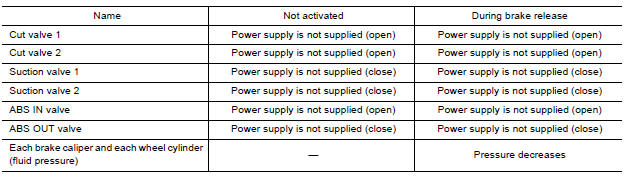
Front RH brake caliper
- Brake fluid is supplied to the front RH brake caliper through the return check valve of the ABS IN valve and the cut valve 1, and returns to the master cylinder.
Front LH brake caliper
- Brake fluid is supplied to the front LH brake caliper through the return check valve of the ABS IN valve and the cut valve 2, and returns to the master cylinder.
Rear RH wheel cylinder
- Brake fluid is supplied to the rear RH wheel cylinder through the return check valve of the ABS IN valve and the cut valve 2, and returns to the master cylinder.
Rear LH wheel cylinder
- Brake fluid is supplied to the rear LH wheel cylinder through the return check valve of the ABS IN valve and the cut valve 1, and returns to the master cylinder.
Component Parts and Function
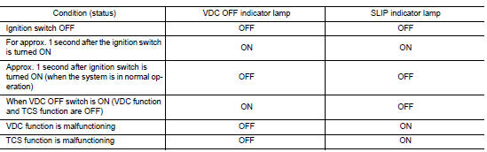
CONDITIONS FOR INDICATOR LAMP ILLUMINATION
- Turns ON when VDC and TCS functions are switched to non-operational status (OFF) by VDC OFF switch.
- Turns ON when ignition switch turns ON and turns OFF when the system is normal, for bulb check purposes.
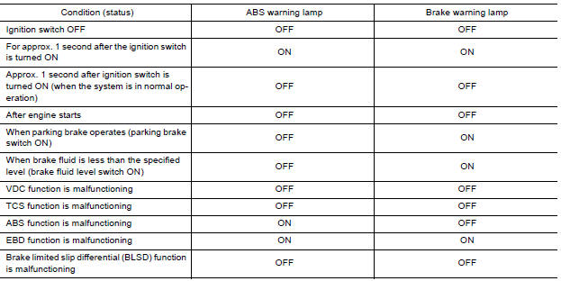
CONDITIONS FOR WARNING LAMP ILLUMINATION
Turns ON when ignition switch turns ON and turns OFF when the system is normal, for bulb check purposes.

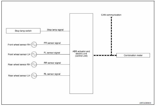
VDC/TCS/ABS : VDC Function
SYSTEM DIAGRAM
SYSTEM DESCRIPTION
- Side slip or tail slip may occur while driving on a slippery road or
intending an urgent evasive driving maneuver.
VDC function detects side slip status using each sensor when side slip or tail slip is about to occur and improves vehicle stability by brake control and engine output control during driving.
- In addition to ABS function, EBD function and TCS function, target side slip amount is calculated according to steering operation amount from steering angle sensor. By comparing this information with vehicle side slip amount that is calculated from information from yaw rate/side G sensor and wheel sensor, vehicle driving conditions (conditions of understeer or oversteer) are judged and vehicle stability is improved by brake force control on all 4 wheels and engine output control.
- VDC function can be switched to non-operational status (OFF) by operating VDC OFF switch. In this case, VDC OFF indicator lamp turns ON.
- Control unit portion automatically improves driving stability by performing brake force control as well as engine output control, by transmitting drive signal to actuator portion according to difference between target side slip amount and vehicle side slip amount
- Brake force control function at braking hard detects driver′s brake operations with the pressure sensor, judges a brake booster′s maximum brake power function by using information from the vacuum sensor, and enhances more powerful braking force by controlling brakes of four wheels.
- VDC warning lamp blinks while VDC function is in operation and indicates to the driver that the function is in operation.
- CONSULT can be used to diagnose the system.
- Fail-safe function is adopted. When a malfunction occurs in VDC function, the control is suspended for VDC function and TCS function. However, ABS function and EBD function operate normally. Refer to BRC "Fail-safe".
INPUT SIGNAL AND OUTPUT SIGNAL
Major signal transmission between each unit via communication lines is shown in the following table.
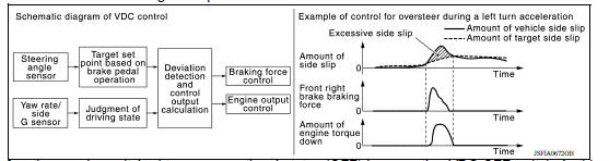
OPERATION CHARACTERISTICS
VDC Function That Prevents Oversteer Tendency
- During cornering, brake force (brake fluid pressure) is applied on front wheel and rear wheel on the outer side of turn. Momentum is generated directing the vehicle toward the outer side of the turn. Oversteer is prevented.
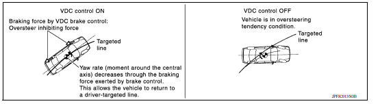
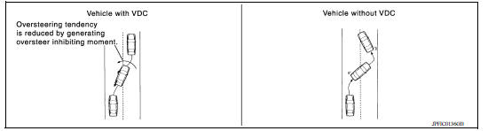
- Changing driving lane on a slippery road, when there may be a tendency to oversteer, engine output is controlled as well as brake force (brake fluid pressure) of 4 wheels. Oversteer tendency decreases.
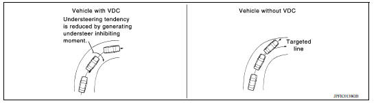
VDC Function That Prevents Understeer Tendency
- During cornering, brake force (brake fluid pressure) is applied on front wheel and rear wheel on the inner side of turn. Momentum is generated directing the vehicle toward the inner side of the turn. Understeer is prevented.
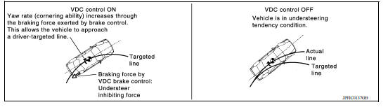
- Applying brakes during cornering on a slippery road, when there may be a tendency to understeer, engine output is controlled as well as brake force (brake fluid pressure) of 4 wheels. Understeer tendency decreases.
VDC/TCS/ABS : TCS Function
SYSTEM DIAGRAM
SYSTEM DESCRIPTION
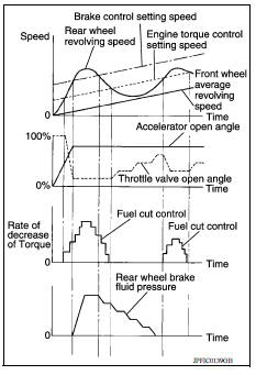
- Wheel spin status of drive wheel is detected by wheel sensor of 4 wheels. Engine output and transmission shift status is controlled so that slip rate of drive wheels is in appropriate level. When wheel spin occurs on drive wheel, ABS actuator and electric unit (control unit) perform brake force control of LH and RH drive wheels (apply brake force by increasing brake fluid pressure of drive wheel) and decrease engine torque by engine torque control. Wheel spin amount decreases. Engine torque is controlled to appropriate level.
- TCS function can be switched to non-operational status (OFF) by operating VDC OFF switch. In this case, VDC OFF indicator lamp turns ON.
- SLIP indicator lamp blinks while TCS function is in operation and indicates to the driver that the function is in operation.
- CONSULT can be used to diagnose the system.
- Fail-safe function is adopted. When a malfunction occurs in TCS
function, the control is suspended for VDC function and TCS function.
However, ABS function and EBD function operate normally.
Refer to BRC "Fail-safe".
INPUT SIGNAL AND OUTPUT SIGNAL
Major signal transmission between each unit via communication lines is shown in the following table.
VDC/TCS/ABS : ABS Function
SYSTEM DIAGRAM
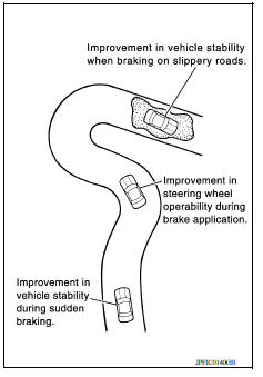
- By preventing wheel lock through brake force (brake fluid pressure) control that is electronically controlled by detecting wheel speed during braking, stability during emergency braking is improved so that obstacles can be easily bypassed by steering operation.
- During braking, control units calculate wheel speed and pseudo-vehicle speed, and transmit pressure increase, hold or decrease signals to actuator portion according to wheel slip status.
- The following effects are obtained by preventing wheel lock during braking.
- Vehicle tail slip is prevented during braking when driving straight.
- Understeer and oversteer tendencies are moderated during braking while cornering.
- Obstacles may be easily bypassed by steering operation during braking.
- CONSULT can be used to diagnose the system.
- Fail-safe function is adopted. When a malfunction occurs in ABS
function, the control is suspended for VDC function, TCS function
and ABS function. However, EBD function operates normally.
Refer to BRC "VDC/TCS/ABS : Fail-safe".
INPUT SIGNAL AND OUTPUT SIGNAL
Major signal transmission between each unit via communication lines is shown
in the following table. 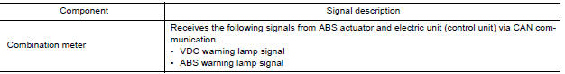
VDC/TCS/ABS : EBD Function
SYSTEM DIAGRAM
- By preventing rear wheel slip increase through rear wheel brake force (brake fluid pressure) control that is electronically controlled when slight skip on front and rear wheels are detected during braking, stability during braking is improved.
- EBD function is expanded and developed from conventional ABS function and corrects rear wheel brake force to appropriate level by electronic control according to load weight (number of passengers).
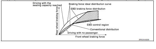
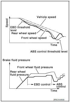
- During braking, control unit portion compares slight slip on front and rear wheels by wheel speed sensor signal, transmits drive signal to actuator portion when rear wheel slip exceeds front wheel slip for the specified value or more, and controls rear wheel brake force (brake fluid pressure) so that increase of rear wheel slip is prevented and slips on front wheel and rear wheel are nearly equalized. ABS control is applied when slip on each wheel increases and wheel speed is the threshold value of ABS control or less.
- CONSULT can be used to diagnose the system.
- Fail-safe function is adopted. When a malfunction occurs in EBD function, the control is suspended for VDC function, TCS function, ABS function and EBD function. Refer to BRC "VDC/TCS/ABS : Fail-safe".
INPUT SIGNAL AND OUTPUT SIGNAL
Major signal transmission between each unit via communication lines is shown
in the following table. 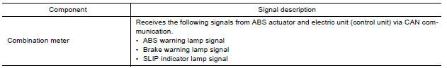
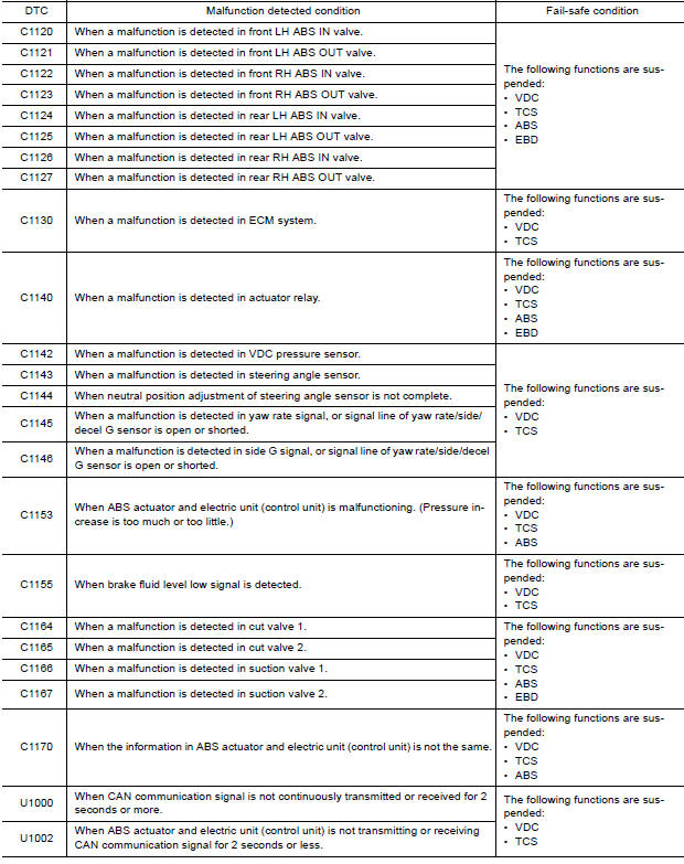
VDC/TCS/ABS : Fail-safe
VDC AND TCS FUNCTIONS
VDC warning lamp in combination meter turns ON when a malfunction occurs in system [ABS actuator and electric unit (control unit)]. The control is suspended for VDC and TCS functions. However, ABS and EBD functions operate normally.
ABS FUNCTION
ABS warning lamp and SLIP indicator lamp in combination meter turn ON when a malfunction occurs in system [ABS actuator and electric unit (control unit)]. The control is suspended for VDC, TCS and ABS functions.
However, EBD functions operate normally.
EBD FUNCTION
ABS warning lamp, brake warning lamp and SLIP indicator lamp in combination meter turn ON when a malfunction occurs in system [ABS actuator and electric unit (control unit)]. The control is suspended for VDC, TCS, ABS and EBD functions.
 Component parts
Component Parts Location 1 ABS actuator and electric unit (control unit) 2 IPDM E/R 3 Brake fluid level switch (view with IPDM E/R removed) 4 Front wheel sensor 5 Rear wheel sensor 6 VDC OFF ...
Diagnosis system [abs actuator
and electric unit (control unit)]
CONSULT Function (ABS) APPLICATION ITEMS CONSULT can display each diagnostic item using the following direct diagnostic modes. ECU IDENTIFICATION ABS actuator and electric uni ...
Other materials:
Transmitter
Exploded View
1. Transmitter (tire pressure sensor) 2. O-ring 3. Valve stem nut
4. Valve core 5. Valve cap 6. Valve stem assembly
: Parts that are replaced as a set
when the tire is replaced.
Removal and Installation
REMOVAL
Remove road wheel and tire assembly using power tool. Refe ...
Steering wheel
Inspection
CHECKING CONDITION OF INSTALLATION
Check installation conditions of steering gear assembly, front
suspension assembly, axle and steering column
assembly.
Check if movement exists when steering wheel is moved up and down, to
the left and right and to the axial
direction.
...
Categories
- Manuals Home
- Nissan Versa Owners Manual
- Nissan Versa Service Manual
- Video Guides
- Questions & Answers
- External Resources
- Latest Updates
- Most Popular
- Sitemap
- Search the site
- Privacy Policy
- Contact Us

0.008