Nissan Versa (N17): Washer pump
Exploded View
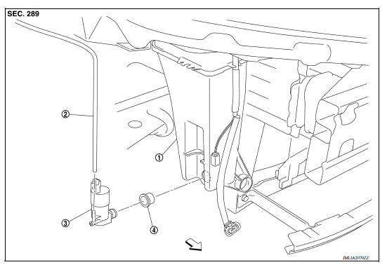
1. Washer tank 2. Front washer tube 3. Washer pump
4. Seal  Front
Front
Removal and Installation
REMOVAL
1. Remove fender protector. Refer to EXT "Removal and Installation".
2. Disconnect the harness connector from the washer pump.
3. Remove front washer tube.
4. Remove washer pump from the washer tank assembly.
5. Remove seal from the washer tank assembly.
INSTALLATION
Installation is in the reverse order of removal.
CAUTION: Do not twist or damage the seal when installing the washer pump.
WASHER NOZZLE & TUBE
Washer System Layout
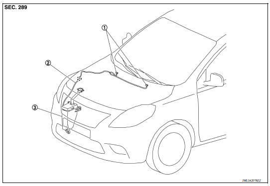
1. Washer nozzle 2. Washer tube 3. Washer tank
Exploded View
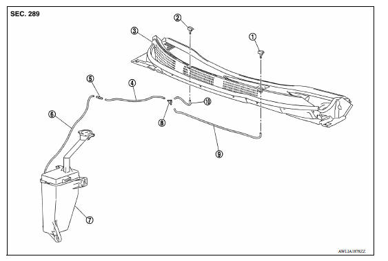
1. Front washer nozzle (LH) 2. Front washer nozzle (RH) 3. Cowl top cover 4. Front washer tube B 5. Joint 6. Front washer tube A 7. Washer tank assembly 8. Check valve 9. Front washer tube C 10. Front washer tube D
 Washer tank
Exploded View 1. Washer tank inlet cap 2. Washer tank assembly Front Removal and Installation REMOVAL 1. Remove fender protector. Refer to EXT "Removal and Installation". 2. Di ...

Other materials:
Engine control system
ENGINE CONTROL SYSTEM : System Diagram
NOTE:
Battery current sensor is used in CVT models.
ENGINE CONTROL SYSTEM : System Description
ECM performs various controls such as fuel injection control and ignition
timing control.
ENGINE CONTROL SYSTEM : Fail Safe
NON DTC RELATED ITEM
...
Service data and specifications
(SDS)
General Specifications
Engine type
HR16DE
Type of clutch control
Hydraulic
Clutch disc
Facing size (Outer dia. × Inner dia. × Thickness)
200 × 140 × 3.1 (7.87 × 5.51 × 0.122)
Recommended clutch fluid
Refer to M ...
Categories
- Manuals Home
- Nissan Versa Owners Manual
- Nissan Versa Service Manual
- Video Guides
- Questions & Answers
- External Resources
- Latest Updates
- Most Popular
- Sitemap
- Search the site
- Privacy Policy
- Contact Us

0.0049