Nissan Versa (N17): Windshield glass
Exploded View
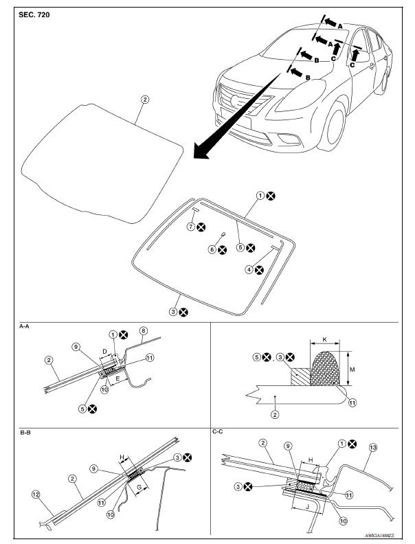
1. Windshield glass molding 2. Windshield glass 3. Dam sealant rubber (lower) 4. Windshield glass holder (LH) 5. Dam sealant rubber (upper) 6. Inside mirror base 7. Windshield glass holder (RH) 8. Roof assembly 9. Glass primer 10. Body primer 11. Adhesive 12. Cowl top cover 13. Body side outer panel D. 10.0 (0.39) G. 19.5 (0.77) H. 8.0 (0.31) J. 19.0 (0.75) K 7.0 (0.28) M 12.0 (0.47)
Removal and Installation
REMOVAL
1. Remove front pillar finishers (LH/RH). Refer to INT "FRONT PILLAR FINISHER : Removal and Installation".
2. Partially remove the headlining (front edge). Refer to INT "Removal and Installation".
3. Remove cowl top covers. Refer to EXT "Removal and Installation".
4. Remove glass using piano wire or power cutting tool (A) and an inflatable pump bag (B) after removing moldings.
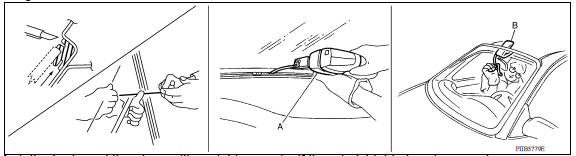
- Mark the body and the glass with matching marks if the windshield glass is reused.
- Apply protective tape around the windshield glass to protect the painted surface from damage.
WARNING: Always wear safety glasses and heavy gloves to help prevent injuries.
CAUTION:
- Be careful not to scratch the glass when removing.
- Be careful not to set or stand the glass on its edge. Small chips may develop into cracks.
INSTALLATION
Installation is in reverse order of removal
CAUTION: Be sure the adjustments of front wiper arms stop location. Refer to WW "WIPER ARM : Adjustment".
- Use a Genuine Nissan Urethane Adhesive Kit (if available) or an equivalent and follow the instructions provided with it.
- The start and finish of the adhesive application shall be located at the middle of glass bottom to assure watertightness.
- Open a door window while the urethane adhesive is curing. This prevents the glass from being forced out by passenger room air pressure when all door windows are closed.
- Inform the customer that the vehicle should remain stationary until the urethane adhesive is completely cured (approximately 24 hours). Curing time varies with temperature and humidity.
WARNING:
- Keep heat and open flames away as primers and adhesive are flammable.
- The materials contained in the kit are harmful if swallowed and may irritate skin and eyes. Avoid contact with the skin and eyes.
- Use in an open, well-ventilated location. Avoid breathing the vapors. They may be harmful if inhaled. Move immediately to an area with fresh air if affected by vapor inhalation.
- Driving the vehicle before the urethane adhesive is completely cured may affect the performance of the windshield in an accident.
CAUTION:
- Do not use an adhesive that is past its usable term. Shelf life of this product is limited to six months after the date of manufacture. Adhere carefully to the expiration or manufacture date printed on the box.
- Keep primers and adhesive in a cool, dry place. Ideally, they should be stored in a refrigerator.
- Do not leave primers or adhesive cartridge unattended with their caps open or off.
- The vehicle should not be driven for 24 hours or more or until the urethane adhesive is completely cured. Curing time varies depending on temperature and humidity. The curing time increases under lower temperature and lower humidity.
Inspection
REPAIRING WATER LEAKAGE FOR WINDSHIELD GLASS
Leakage can be repaired without removing the windshield glass.
Determine the extent of leakage if water is leaking between the urethane adhesive material and body or glass.
This can be done by applying water to the windshield area while pushing glass outward.
Apply primer (if necessary) and then urethane adhesive to the leakage point to stop the leakage.
 Squeak and rattle trouble diagnoses
Rear window glass
Exploded View 1. Rear window glass 2. Rear window glass holder (RH) 3. Dam sealant rubber (upper) 4. Rear window glass holder (LH) 5. Dam sealant rubber (lower) 6. Glass primer 7. Adhesive 8 ...
Other materials:
Break-in schedule
CAUTION
During the first 1,200 miles (2,000 km),
follow these recommendations to obtain
maximum engine performance and ensure
the future reliability and economy of your
new vehicle. Failure to follow these recommendations
may result in shortened
engine life and reduced engine
performance.
...
Spark plug
Exploded View
1. Ignition coil 2. Spark plug
Removal and Installation
REMOVAL
1. Remove ignition coil.
CAUTION:
Do not drop or shock ignition coil.
2. Remove spark plug using a suitable tool.
Diameter (a) : 14 mm (0.55 in)
CAUTION:
Do not drop or shock spark plug.
INSPECTION AFTER REM ...
Categories
- Manuals Home
- Nissan Versa Owners Manual
- Nissan Versa Service Manual
- Video Guides
- Questions & Answers
- External Resources
- Latest Updates
- Most Popular
- Sitemap
- Search the site
- Privacy Policy
- Contact Us

0.005