Nissan Versa (N17): A/T control system
A/T control system : system diagram
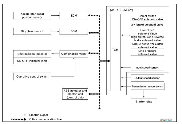
A/T control system : system description
SYSTEM DESCRIPTION
- The A/T senses vehicle operating conditions through various sensors or signals. It always controls the optimum shift position and reduces shifting and lock-up shocks.
- Receives input signals transmitted from various switches and sensors.
- Determines required line pressure, shifting point, lock-up operation, etc.
- Transmits required output signals to the respective solenoids.
INPUT/OUTPUT SIGNAL CHART
|
Sensor (or signal) |
 |
TCM function |
 |
Actuator |
| Engine speed signal Engine torque signal Accelerator pedal position signal Closed throttle position signal Stop lamp switch signal Transmission range switch O/D switch signal A/T fluid temperature sensor Input speed sensor Output speed sensor Vehicle speed signal | Line pressure control (TM) Shift change control (TM) Shift pattern control (TM) Lock-up control (TM) Fail-safe control (TM) Self-diagnosis (TM) CONSULT communication line (TM) CAN communication line (TM) | Line pressure solenoid valve Torque converter clutch solenoid valve Low clutch solenoid valve 2-4 brake solenoid valve High clutch/low & reverse brake solenoid valve Select switch ON-OFF solenoid valve Shift position indicator O/D OFF indicator lamp |
INPUT/OUTPUT SIGNAL OF TCM
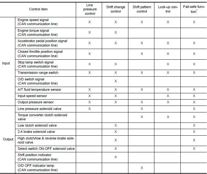
*: If these input and output signals are different, the TCM triggers the fail-safe function.
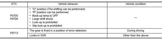
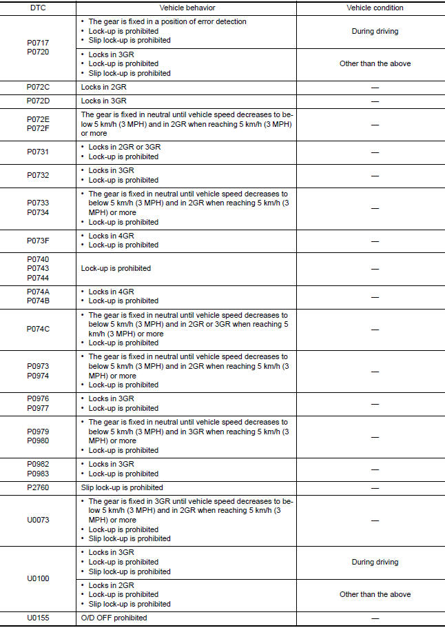
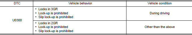
A/T control system : fail-safe
TCM is equipped with an electrical fail-safe mode. The operation can be continued even if the signal circuit of the main electronically controlled input/output parts are damaged.
If the vehicle shows following behaviors including "poor acceleration", a malfunction of the applicable system is detected by TCM and the vehicle may be in a fail-safe mode. At this time, check the DTC code and perform inspection and repair according to the malfunction diagnosis procedures.
FAIL-SAFE FUNCTION
A/T control system : protection control
The TCM becomes the protection control status temporarily to protect the safety when the safety of TCM and transmission is lost. It automatically returns to the normal status if the safety is secured.
The TCM is equipped with the following protection control.
REVERSE INHIBIT CONTROL
Intercepts the torque transmission and shifts to the neutral status if the selector lever is shifted to "R" position while the vehicle moves forward at the vehicle speed 10 km/h (7 MPH) or more.
| Operation detection conditions |
|
| Control when activated | Neutral |
| Recovery condition |
|
| Vehicle behavior |
|
TCM HIGH TEMPERATURE PROTECTION CONTROL
When the ATF becomes hot, the shifting pattern is changed for preventing fluid temperature rise.
| Operation detection conditions | ATF temp.: 125C (257F) or more |
| Control when activated | Change the shift pattern so that higher upshift may be achieved. |
| Recovery condition |
|
| Vehicle behavior | Upshifts at a higher vehicle speed than usual. |
TORQUE-DOWN CONTROL WHEN CONTINUOUS STALL OCCURS IN D POSITION
If the accelerator pedal is continually depressed for a certain length of time when the selector lever is in the "D" position and the vehicle is parked, the engine output is limited for protecting the transaxle.
| Operation detection conditions | The following conditions continue for 20 seconds or more
|
| Control when activated | Limits engine output |
| Recovery condition |
|
| Vehicle behavior |
|
O/D PROHIBIT CONTROL AT LOW TEMPERATURES
When the ATF temperature is low immediately after engine start, shifting to 4GR is prohibited for protecting the transaxle and allowing the exhaust gas characteristics to warm up quickly.
| Operation detection conditions |
|
| Control when activated | 4GR prohibited |
| Recovery condition | Less than 130 seconds following IGN ON
|
| Vehicle behavior | Shifts up only as far as 3GR. |
 Transaxle
Transaxle : cross-sectional view 1. Converter housing 2. Oil pump 3. Low clutch 4. Rear planetary gear 5. Low & reverse brake 6. Front planetary gear 7. Low one-way clutch 8. High clutch ...
Line pressure control
Line pressure control : system diagram Line pressure control : system description When an engine and A/T integrated control signal (engine torque) equivalent to the engine drive force is ...
Other materials:
Seat belt retractor
SEAT BELT RETRACTOR : Removal and Installation
REMOVAL
CAUTION:
Before servicing, turn ignition switch OFF, disconnect battery negative terminal
and wait at least three
minutes.
Disconnect both the negative and positive battery cables, then wait at
least three minutes. Refer to PG " ...
Inside handle
INSIDE HANDLE : Removal and Installation
REMOVAL
1. Remove front door finisher. Refer to INT "Removal and Installation".
2. Remove upper side of sealing screen.
NOTE:
Cut the butyl tape so that some parts of the butyl tape remain on the sealing
screen, if the sealing screen
is re ...
Categories
- Manuals Home
- Nissan Versa Owners Manual
- Nissan Versa Service Manual
- Video Guides
- Questions & Answers
- External Resources
- Latest Updates
- Most Popular
- Sitemap
- Search the site
- Privacy Policy
- Contact Us

0.0068