Nissan Versa (N17): C1601 Battery power supply
DTC Logic
DTC DETECTION LOGIC
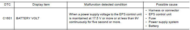
DTC CONFIRMATION PROCEDURE
1.PRECONDITIONING
If "DTC CONFIRMATION PROCEDURE" has been previously conducted, always turn ignition switch OFF and wait at least 10 seconds before conducting the next test.
>> GO TO 2.
2.DTC REPRODUCTION PROCEDURE
With CONSULT
- Turn the ignition switch OFF to ON.
- Perform "EPS" self-diagnosis.
Is DTC "C1601" detected?
YES >> Proceed to diagnosis procedure. Refer to STC "Diagnosis Procedure".
NO >> Inspection End.
Diagnosis Procedure
Regarding Wiring Diagram information, refer to STC "Wiring Diagram".
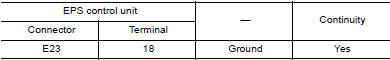
1.CHECK EPS CONTROL UNIT GROUND CIRCUIT
- Turn ignition switch OFF.
- Disconnect EPS control unit harness connector.
- Check continuity between EPS control unit harness connector terminal and
ground.
- Connect EPS control unit harness connector.
Is the inspection result normal?
YES >> GO TO 2.
NO >> Repair open circuit or short to ground or short to power in harness or connectors.
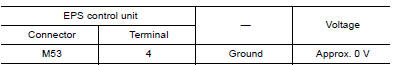
2.CHECK EPS CONTROL UNIT POWER SUPPLY CIRCUIT (1)
1. Check voltage between EPS control unit
harness connector terminal and ground.
2. Turn ignition switch ON.
CAUTION: Never start the engine.
3. Check voltage between EPS control unit
harness connector and ground. 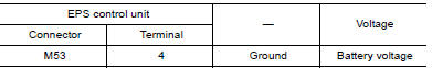
Is the inspection result normal?
YES >> GO TO 4.
NO >> GO TO 3.
3.CHECK EPS CONTROL UNIT POWER SUPPLY CIRCUIT (2)
- Turn ignition switch OFF.
- Check the 10A fuse (No. 5).
- Check the harness for open or short between EPS control unit harness connector M53 terminal 4 and the 10A fuse (No. 5).
Is the inspection result normal?
YES >> Perform the trouble diagnosis for ignition power supply circuit. Refer to PG "Wiring Diagram - Ignition Power Supply -".
NO >> Repair or replace malfunctioning component.
4.CHECK EPS CONTROL UNIT POWER SUPPLY CIRCUIT (3)
- Turn ignition switch OFF.
- Check voltage between EPS control unit harness connector terminal and
ground.
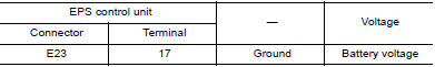
3. Turn ignition switch ON.
CAUTION: Never start the engine.
4. Check voltage between EPS control unit
harness connector and ground. 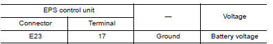
Is the inspection result normal?
YES >> GO TO 6.
NO >> GO TO 5.
5.CHECK EPS CONTROL UNIT POWER SUPPLY CIRCUIT (4)
- Turn ignition switch OFF.
- Check the 60A fusible link (J).
- Check the harness for open or short between EPS control unit harness connector E23 terminal 17 and the 60A fusible link (J).
Is the inspection result normal?
YES >> Perform the trouble diagnosis for power supply circuit. Refer to PG "Wiring Diagram - Battery Power Supply -".
NO >> Repair or replace malfunctioning component.
6.CHECK CONNECTOR
- Turn ignition switch OFF.
- Disconnect torque sensor harness connector.
- Check terminal for deformation, disconnection, looseness, and so on. If any malfunction is found, repair or replace terminal.
Is the inspection result normal?
YES >> Replace EPS control unit. Refer to STC "Removal and Installation".
NO >> Repair or replace malfunctioning component.
 Diagnosis and repair workflow
Other materials:
Head restraints/headrests
WARNING
Head restraints/headrests supplement
the other vehicle safety systems. They may
provide additional protection against injury
in certain rear end collisions. Adjustable
head restraints/headrests must be
adjusted properly, as specified in this section.
Check the adjustment after someo ...
Control panel buttons - color screen with Navigation System (if so equipped)
WARNING
Positioning of the heating or air conditioning
controls and display controls
should not be done while driving in order
that full attention may be given to
the driving operation.
Do not disassemble or modify this system.
If you do, it may result in accidents,
fire, or elec ...
Categories
- Manuals Home
- Nissan Versa Owners Manual
- Nissan Versa Service Manual
- Video Guides
- Questions & Answers
- External Resources
- Latest Updates
- Most Popular
- Sitemap
- Search the site
- Privacy Policy
- Contact Us

0.0087