Nissan Versa (N17): Clutch master cylinder
Exploded View
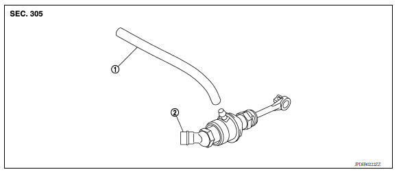
1. Reservoir hose 2. Master cylinder
Removal and Installation
CAUTION:
- Do not spill clutch fluid onto painted surfaces. If fluid spills, wipe up immediately and wash the affected area with water.
- Do not disassemble clutch master cylinder.
NOTE: When removing components such as hoses, tubes/lines, etc., cap or plug openings to prevent fluid from spilling.
REMOVAL
- Remove battery. Refer to PG, "Removal and Installation".
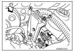
- Remove IPDM E/R bracket bolts (A) and nut (B).
- Remove IPDM E/R bracket (1).
 : Front

4. Remove ECM bracket nuts (A).
 : Front
5. Remove master cylinder rod end (
 ) from clutch pedal.
6. Use one of the following methods to remove hose from master cylinder.
- Drain clutch fluid from reservoir tank and remove hose. Refer to CL, "Draining".
- Remove hose from master cylinder.

7. Pull up the lock pin (1) from connector of master cylinder (2) and separate clutch tube (3).
8. Rotate master cylinder clockwise by 45 degrees and then remove master cylinder from the vehicle.

INSTALLATION
CAUTION: Do not spill clutch fluid onto painted surfaces. If fluid spills, wipe up immediately and wash the affected area with water.
- With the nipple (1) rotated clockwise by 45 degrees, insert clutch master cylinder into the mounting hole. Rotate the clutch master cylinder counterclockwise by 45 degrees (A) as shown to secure it. At this time, nipple is in the upward (B).
- Install master cylinder rod end to clutch pedal.
CAUTION: Press master cylinder rod end into clutch pedal until it stops.
- Install reservoir hose to master cylinder.
- Press down the lock pin into connector of master cylinder until it stops.
- Install clutch tube into connector of master cylinder until it stops.
- Fill with clutch fluid and bleed clutch hydraulic system. Refer to CL "Refilling".
- Installation of the remaining components is in the reverse order of removal.
Inspection and Adjustment
INSPECTION AFTER INSTALLATION
Check for fluid leakage and check the fluid level. Refer to CL, "Inspection".

 Clutch pedal
Exploded View 1. Clutch pedal 2. Pedal stopper rubber 3. Pedal pad 4. Clip 5. Clutch interlock switch Removal and Installation REMOVAL Remove the instrument lower panel LH. Refer to IP, ...
Clutch piping
Exploded View 1. CSC (Concentric Slave Cylinder) 2. Clutch tube 3. Clutch damper 4. Bracket 5. Master cylinder Hydraulic Layout 1. Clutch tube 2. Lock pin 3. CSC (concentric slave cylinder ...
Other materials:
Bluetooth Hands-Free Phone System without Navigation System (Type A) (if so
equipped)
WARNING
Use a phone after stopping your vehicle
in a safe location. If you have to use a
phone while driving, exercise extreme
caution at all times so full attention may
be given to vehicle operation.
If you are unable to devote full attention
to vehicle operation while talking on
...
Shift control
SHIFT CONTROL : System Description
SYSTEM DIAGRAM
DESCRIPTION
To select the gear ratio that can give the driving force to meet driver's
intent or vehicle situation, the vehicle
driving condition such as vehicle speed or accelerator pedal position is
detected and the most appropriate
g ...
Categories
- Manuals Home
- Nissan Versa Owners Manual
- Nissan Versa Service Manual
- Video Guides
- Questions & Answers
- External Resources
- Latest Updates
- Most Popular
- Sitemap
- Search the site
- Privacy Policy
- Contact Us

0.0053