Nissan Versa (N17): Component parts
POWER DOOR LOCK SYSTEM
POWER DOOR LOCK SYSTEM : Component Parts Location
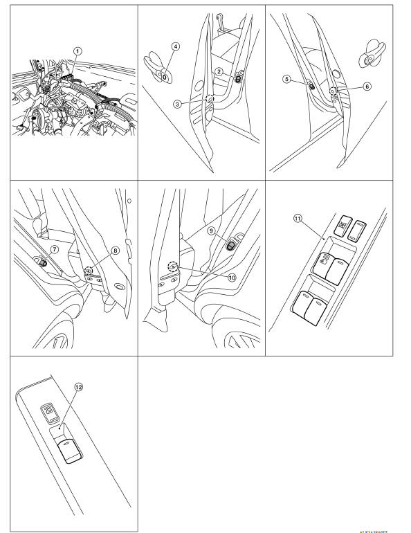
1. BCM (shown with instrument panel removed) 2. Front door switch LH 3. Front door lock actuator LH 4. Front door lock key cylinder switch LH 5. Front door switch RH 6. Front door lock actuator RH 7. Rear door switch RH 8. Rear door lock actuator RH 9. Rear door lock switch LH 10. Rear door lock actuator LH 11. Main power window and door lock/ unlock switch 12. Power window and door lock/unlock switch RH
POWER DOOR LOCK SYSTEM :
Component Description
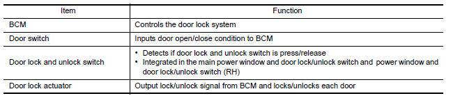
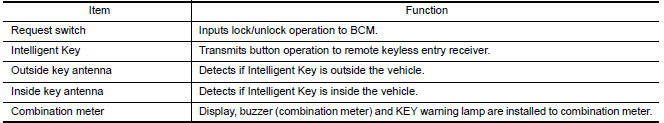
INTELLIGENT KEY SYSTEM
INTELLIGENT KEY SYSTEM : Component Parts Location
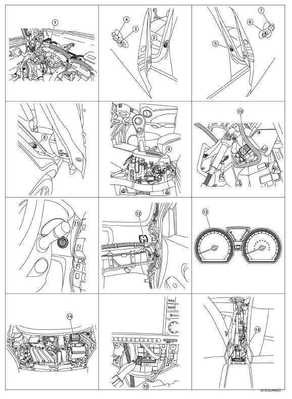
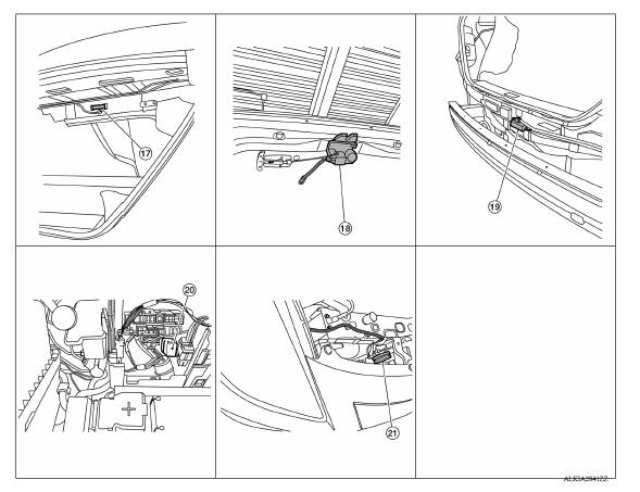
1. BCM (view with instrument panel removed) 2. Front door switch LH 3. Door request switch LH 4. Outside key antenna LH 5. Front door switch RH 6. Door request switch RH 7. Outside key antenna RH 8. Rear door switch RH (rear door switch LH similar) 9. CVT shift selector (park position switch) (view with center console removed) 10. Brake switch 11. Push-button ignition switch 12. Remote keyless entry receiver (view with instrument panel removed) 13. Combination meter (type B) 14. IPDM E/R 15. Inside key antenna (center) 16. Inside key antenna (console) (view with center console removed) 17. Inside key antenna (trunk room) 18. Trunk room lamp switch 19. Outside key antenna (rear bumper) (view with rear bumper facia removed) 20. Horn relay (shown with IPDM E/R removed) 21. Horn
INTELLIGENT KEY SYSTEM :
Component Description 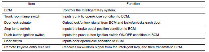
TRUNK LID OPENER SYSTEM
TRUNK LID OPENER SYSTEM : Component Parts Location
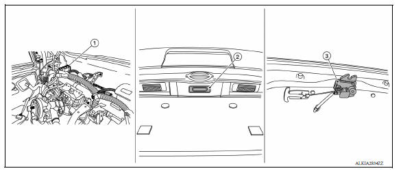
1. BCM (view with instrument panel removed) 2. Trunk lid switch 3. Trunk lid lock assembly (trunk lid opener actuator and trunk lid switch)
TRUNK LID OPENER SYSTEM :
Component Description 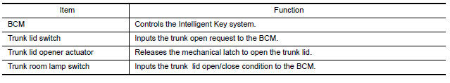
 Precautions
System (power door lock system)
System Diagram System Description DOOR LOCK FUNCTION The door lock and unlock switch (driver side) is built into power window main switch. The door lock and unlock switch (pa ...
Other materials:
P0506 ISC system
Description
The ECM controls the engine idle speed to a specified level through the fine
adjustment of the air, which is let
into the intake manifold, by operating the electric throttle control actuator.
The operating of the throttle valve is
varied to allow for optimum control of the engine ...
Diagnosis system [abs actuator
and electric unit (control unit)]
CONSULT Function (ABS)
APPLICATION ITEMS
CONSULT can display each diagnostic item using the following direct
diagnostic modes.
ECU IDENTIFICATION
ABS actuator and electric unit (control unit) part number is displayed.
SELF DIAGNOSTIC RESULT
Operation Procedure
Before p ...
Categories
- Manuals Home
- Nissan Versa Owners Manual
- Nissan Versa Service Manual
- Video Guides
- Questions & Answers
- External Resources
- Latest Updates
- Most Popular
- Sitemap
- Search the site
- Privacy Policy
- Contact Us

0.0078