Nissan Versa (N17): Compressor
Exploded View
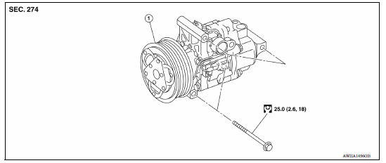
1. Compressor
Removal and Installation
CAUTION: Perform oil return operation before each refrigeration system disassembly. However, if a large amount of refrigerant or oil is detected, do not perform oil return operation. Refer to HA "Perform Oil Return Operation".
REMOVAL
- Use refrigerant collecting equipment (for HFC-134a) to discharge the refrigerant. Refer to HA "Recycle Refrigerant".
- Remove the high and low-pressure flexible hose bolts and disconnect low-pressure flexible hose and high-pressure flexible hose from the compressor. CAUTION: Cap or wrap the joint of the A/C piping and compressor with suitable material such as vinyl tape to avoid the entry of air.
- Remove the engine under cover. Refer to EXT "Removal and Installation".
- Remove drive belt. Refer to EM "Removal and Installation".
- Disconnect the harness connector from the compressor (magnet clutch).
- Remove compressor bolts and the compressor.
INSTALLATION
Installation is in the reverse order of removal.
CAUTION:
- Do not reuse O-rings.
- Apply A/C oil to the O-rings of the low-pressure flexible hose and high-pressure flexible hose for installation.
- Perform oil adjusting procedure before installing new compressor. Refer to HA "Oil Adjusting Procedure for Components Replacement Except Compressor".
- After charging the A/C refrigerant, check for leaks. Refer to HA "Leak Test".
- Check tension of the drive belt after installing compressor. Refer to EM "Inspection".
Inspection
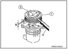
CHECK DISC TO PULLEY CLEARANCE
Check the clearance (B) between pulley assembly (1) and clutch disc (2) along the entire periphery with a feeler gauge (A).
Clearance : Refer to HA "Compressor".
If specified clearance is not obtained, replace adjusting spacer and readjust.
 Performance test
Inspection INSPECTION PROCEDURE Connect recovery/recycling/recharging equipment (for HFC-134a) or manifold gauge. Start the engine, and set to the following condition. Test condition&nbs ...
Condenser
Exploded View 1. Condenser 2. O-rings 3. Liquid tank bracket 4. Liquid tank 5. O-ring 6. Refrigerant pressure sensor Removal and Installation CAUTION: Perform oil return operation before each ...
Other materials:
Oil filter
Removal and Installation
REMOVAL
Remove engine under cover.
Drain engine oil.
Remove oil filter using Tool (A).
: Front
Tool number : KV10115801 (J38956)
WARNING:
Be careful not to get burned; engine and engine oil may be
hot.
CAUTION:
When removing, prepare a shop cl ...
Power supply and ground circuit
Diagnosis Procedure
Regarding Wiring Diagram information, refer to BCS "Wiring Diagram".
1.CHECK FUSES AND FUSIBLE LINK
Check that the following fuses and fusible link are not blown.
Is the fuse blown?
YES >> Replace the blown fuse or f ...
Categories
- Manuals Home
- Nissan Versa Owners Manual
- Nissan Versa Service Manual
- Video Guides
- Questions & Answers
- External Resources
- Latest Updates
- Most Popular
- Sitemap
- Search the site
- Privacy Policy
- Contact Us

0.005