Nissan Versa (N17): Control cable
Exploded View
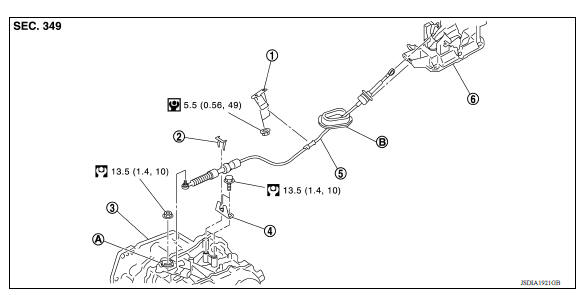
1. Bracket B 2. Lock plate 3. Transaxle assembly 4. Bracket A 5. Control cable 6. CVT shift selector assembly A: Manual lever B: Grommet
Removal and Installation
CAUTION: Always apply the parking brake before performing removal and installation.
REMOVAL
- Remove the battery. Refer to PG "Removal and Installation".
- Remove the TCM and bracket. Refer to TM "Removal and Installation".
- Remove the IPDM E/R. Refer to PCS "Removal and Installation".
- Remove the battery tray and bracket.
- Remove the center console. Refer to IP "Removal and Installation".
- Remove the control cable from the CVT shift selector assembly.
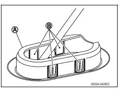
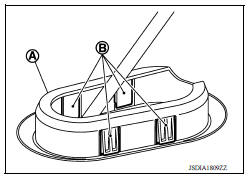
- Disengage the pawls (B) of the grommet (A), and pull downward to remove.
- Remove the control cable nut from the manual lever.
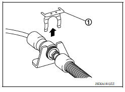
9. Remove the lock plate (1).
10. Lift up the heat plate.
11. Remove the control cable (1) from the bracket (2).
 Front
Front
12. Remove the control cable from the vehicle.
13. Remove bracket.
INSTALLATION
Installation is in the reverse order of removal.
- From below the vehicle, press the grommet (A) into place until the
pawls (B) make a click sound.
CAUTION: Check that pulling down on the grommet does not disconnect it.
- Pay attention to the following when connecting the control cable to the CVT shift selector.
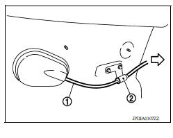
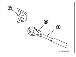
- When connecting the control cable (1) to the CVT shift selector assembly (2), face the grooved surface of the rib (A) up and insert the control cable until it stops.
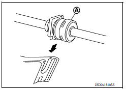
2. Install the socket (A) onto the CVT shift selector assembly.
CAUTION:
- Insert the socket into the CVT shift selector assembly, then push it firmly in place.
- Check that pulling on the socket does not disconnect it.
Inspection
INSPECTION AFTER INSTALLATION
Check the CVT position. If a malfunction is found, adjust the CVT position. Refer to TM "Inspection and Adjustment".
 CVT Shift selector
Exploded View 1. Shift selector handle 2. Lock pin 3. Shift selector handle cover 4. Position indication panel 5. CVT shift selector assembly ...
Key interlock cable
Exploded View 1. CVT shift selector assembly 2. Key interlock cable A: Key cylinder B: Lock plate C: Clip Removal and Installation REMOVAL CAUTION: Always apply the parking brake before pe ...
Other materials:
If your vehicle overheats
If your vehicle is overheating (indicated by an
extremely high temperature gauge reading (if so
equipped), a red high temperature warning light
(if so equipped) ), or if you feel a
lack of
engine power, detect abnormal noise, etc. take
the following steps.
WARNING
Do not continue to driv ...
Cylinder block
Exploded View
1. Crankshaft position sensor cover 2. Crankshaft position sensor (POS) 3.
Oring
4. Drain plug 5. Cylinder block 6. Oil level gauge
7. Oil level gauge guide 8. Oring 9. Knock sensor 10. Oil temperature sensor
11. Oil pressure sensor 12. Oil jet
13. Top ring 14. Second ring ...
Categories
- Manuals Home
- Nissan Versa Owners Manual
- Nissan Versa Service Manual
- Video Guides
- Questions & Answers
- External Resources
- Latest Updates
- Most Popular
- Sitemap
- Search the site
- Privacy Policy
- Contact Us

0.0068