Nissan Versa (N17): Diagnosis description
Diagnosis description : 1 trip detection diagnosis and 2 trip detection diagnosis
NOTE: "Start the engine and turn OFF the ignition switch after warm-up." This is defined as 1 trip.
1 TRIP DETECTION DIAGNOSIS
When initial malfunction is detected, TCM memorizes DTC. In these diagnoses, some illuminate MIL and some do not. Refer to TM, "DTC Index".
2 TRIP DETECTION DIAGNOSIS
When initial malfunction is detected, TCM memorizes DTC of the 1st trip. MIL does not light at this stage. <1 trip> If the same malfunction is detected again in next driving, TCM memorizes DTC. When DTC is memorized, MIL lights. <2 trip> "Trip" of the "2 trip detection diagnosis" indicates the driving mode that executes self-diagnosis during driving.
×: Check possible -: Check not possible
| Item | DTC at the 1st trip | DTC | MIL | |||
| Display at the 1st trip | Display at the 2nd trip | Display at the 1st trip | Display at the 2nd trip | Illumination at the 1st trip | Illumination at the 2nd trip | |
| 1 trip detection diagnosis (Refer to TM, "DTC Index") | - | - | × | - | × | - |
| 2 trip detection diagnosis (Refer to TM, "DTC Index") | × | - | - | × | - | × |
Diagnosis description : dtc and dtc of 1st trip
2 TRIP DETECTION DIAGNOSIS THAT ILLUMINATES MIL
- The DTC number of the 1st trip is the same as the DTC number.
- When a malfunction is detected at the 1st trip, TCM memorizes DTC of the 1st trip. MIL does not light at this stage. If the same malfunction is not detected at the 2nd trip (conforming to necessary driving conditions), DTC at the 1st trip is erased from TCM. If the same malfunction is detected at the 2nd trip, TCM memorizes DTC and MIL lights at the same time.
- The DTC of the 1st trip is specified in Service $01 of SAE J1979/ISO 15031-5. Since detection of DTC at the 1st trip does not illuminate MIL, warning for a problem is not given to a driver.
- For procedure to delete DTC and 1st trip DTC from TCM, refer to TM, "CONSULT Function".
- If DTC of the 1st trip is detected, it is necessary to check the cause according to the "Diagnosis flow". Refer to TM, "Work Flow".
Diagnosis description : malfunction indicator lamp (MIL)
- TCM not only detects DTC, but also sends the MIL signal to ECM through CAN communication. ECM sends the MIL signal to the combination meter through CAN communication according to the signal, and illuminates MIL.
- For malfunction indicator lamp (MIL) description, refer to EC, "Malfunction Indicator Lamp (MIL)".
Diagnosis description : counter system
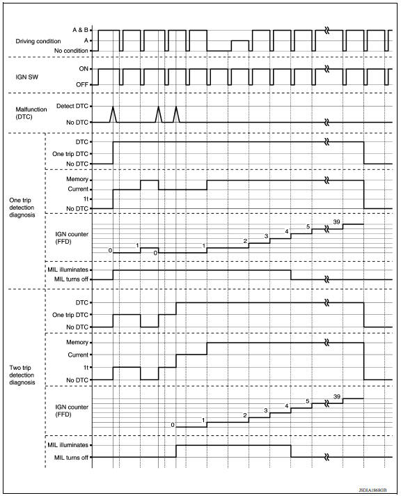
RELATION BETWEEN DTC AT 1ST TRIP/DTC/MI AND DRIVING CONDITIONS (FOR 2 TRIP DETECTION DIAGNOSIS THAT ILLUMINATES MIL)
- When initial malfunction is detected, TCM memorizes DTC of the 1st trip. MIL does not light at this stage.
- If the same malfunction is detected at the 2nd trip, TCM memorizes DTC and MIL lights at the same time.
- Then, MIL goes after driving the vehicle for 3 trips under "Driving Pattern B" without malfunction.
- DTC is displayed until 40 trips of "Driving Pattern A" are satisfied
without detecting the same malfunction.
DTC is erased when 40 trips are satisfied.
- When the self-diagnosis result is acceptable at the 2nd trip (conforming to driving pattern B), DTC of the 1st trip is erased.
COUNTER SYSTEM LIST 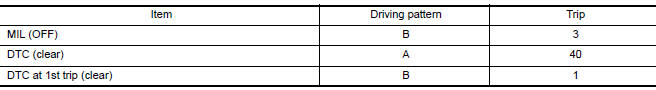
DRIVING CONDITION
Driving Pattern A
Driving pattern A is the driving condition that provides warm-up.
In specific, count-up is performed when all of the following conditions are satisfied.
- Engine speed reaches 400 rpm or more.
- Engine coolant temperature rises by 20C (36F) or more after starting the engine.
- Engine coolant temperature reaches 70C (158F) or more.
- The ignition switch is turned from ON to OFF.
NOTE:
- If the same malfunction is detected regardless of the driving condition, reset the A counter.
- When the above is satisfied without detecting the same malfunction, count up the A counter.
- When MIL goes off due to the malfunction and the A counter reaches 40, the DTC is erased.
Driving Pattern B
- Driving pattern B is the driving condition that performs all diagnoses
once.
In specific, count-up is performed when all of the following conditions are satisfied.
- Engine speed reaches 400 rpm or more.
- Engine coolant temperature reaches 70C (158F) or more.
- Vehicle speed of 70 - 120 km/h (44 - 75 MPH) is maintained for 60 seconds or more under the control of closed loop.
- Vehicle speed of 30 - 60 km/h (19 - 37 MPH) is maintained for 10 seconds or more under the control of closed loop.
- Under the closed loop control condition, the following state reaches 12 seconds or more in total: Vehicle speed of 4 km/h (2 MPH) or less with idling condition.
- A lapse of 22 minutes or more after engine start.
- The state of driving at 10km/h (6 MPH) or more reaches 10 minutes or more in total.
- The ignition switch was changed from ON to OFF.
NOTE:
- If the same malfunction is detected regardless of the driving condition, reset the B counter.
- When the above is satisfied without detecting the same malfunction, count up the B counter.
- When the B counter reaches 3 without malfunction, MIL goes off.
- When the B counter is counted once without detecting the same malfunction after TCM memorizes DTC of the 1st trip, DTC of the 1st trip is erased.
TIME CHART
 Lock-up control
Lock-up control : system diagram Lock-up control : system description The torque converter clutch piston in the torque converter is engaged to eliminate torque converter slip to increa ...
Consult function
APPLICATION ITEMS Diagnostic test mode Function Work Support This mode enables a technician to adjust some devices faster and more accurately. Self Diagnostic Resul ...
Other materials:
Standard maintenance
The following tables show the standard maintenance
schedule. Depending upon weather and
atmospheric conditions, varying road surfaces,
individual driving habits and vehicle usage, additional
or more frequent maintenance may be required.
After 120,000 miles
(192,000 km)/144 months, continue m ...
Unexpected pedal reaction
Diagnosis Procedure
1.CHECK BRAKE PEDAL STROKE
Check brake pedal stroke. Refer to BR "Inspection and Adjustment".
Is the stroke too big?
YES >>
Bleed air from brake line and hose. Refer to BR "Bleeding Brake System".
Check brake pedal, brake booster, and master cy ...
Categories
- Manuals Home
- Nissan Versa Owners Manual
- Nissan Versa Service Manual
- Video Guides
- Questions & Answers
- External Resources
- Latest Updates
- Most Popular
- Sitemap
- Search the site
- Privacy Policy
- Contact Us

0.014