Nissan Versa (N17): P1586 G Sensor
DTC Logic
DTC DETECTION LOGIC
| DTC | Trouble diagnosis name | DTC detection condition | Possible causes |
| P1586 | G Sensor Circuit Electrical | When the following diagnosis conditions are
satisfied and the detection conditions are satisfied
twice in the same DC: - Diagnosis conditions - While driving - TCM power supply voltage: More than 11 V - Detection condition - The G sensor detection voltage is 0.7 V or less continuously for 5 seconds or more. |
- Harness or connector
(G sensor circuit) - G sensor |
| When the following diagnosis conditions are
satisfied and the detection conditions are satisfied
twice in the same DC: - Diagnosis conditions - While driving - TCM power supply voltage: More than 11 V - Detection condition - The G sensor detection voltage is 3.2 V or more continuously for 5 seconds or more |
NOTE: DC stands for "DRIVING CYCLE" and indicates a series of driving cycle of "Ignition switch OFF → ON → driving → OFF".
DTC CONFIRMATION PROCEDURE
CAUTION: Be careful of the driving speed.
1.PREPARATION BEFORE WORK
If another "DTC CONFIRMATION PROCEDURE" occurs just before, turn ignition switch OFF and wait for at least 10 seconds, then perform the next test.
>> GO TO 2.
2.CHECK DTC DETECTION
With CONSULT
- Start the engine.
- Drive the vehicle for 10 seconds or more.
- Stop the vehicle.
CAUTION: Never stop the engine.
- Repeat step 2 through 3.
- Check the DTC.
Is "P1586" detected?
YES >> Go to TM "Diagnosis Procedure".
NO >> INSPECTION END
Diagnosis Procedure
1.CHECK G SENSOR SIGNAL
With CONSULT
- Park the vehicle on a level surface.
- Turn ignition switch ON.
- Select "Data Monitor" in "TRANSMISSION".
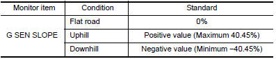
- Select "G SEN SLOPE".
- Swing the vehicle and check if value varies between −40.45% and 40.45%.
Is the inspection result normal?
YES >> GO TO 2.
NO >> GO TO 3.
2.G SENSOR CALIBRATION (PART 1)
With CONSULT
- Select "Self Diagnostic Results" in "TRANSMISSION".
- Touch "Erase".
>> Perform "G SENSOR CALIBRATION". Refer to TM "Work Procedure".
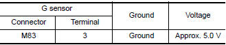
3.CHECK SENSOR POWER SUPPLY
- Turn ignition switch OFF.
- Disconnect G sensor connector.
- Turn ignition switch ON.
- Check voltage between G sensor harness connector terminal and ground.
Is the inspection result normal?
YES >> GO TO 4.
NO >> GO TO 8.
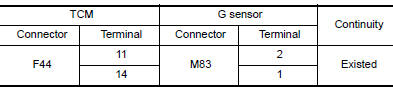
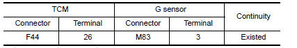
4.CHECK CIRCUIT BETWEEN TCM AND G SENSOR (PART 1)
- Turn ignition switch OFF.
- Disconnect TCM connector.
- Check continuity between TCM harness connector terminals and G sensor
harness connector terminals.
Is the inspection result normal?
YES >> GO TO 5.
NO >> Repair or replace malfunctioning parts.
5.CHECK CIRCUIT BETWEEN TCM AND G SENSOR (PART 2)
Check continuity between TCM harness connector terminals and ground. 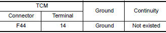
Is the inspection result normal?
YES >> GO TO 6.
NO >> Repair or replace malfunctioning parts.
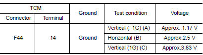
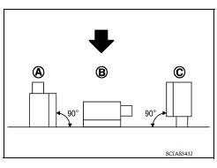
6.CHECK G SENSOR
- Remove G sensor. TM "Removal and Installation".
- Connect the all connectors.
- Turn ignition switch ON.
- Check voltage between TCM harness connector terminal and ground.
 : Direction of gravitational
force
: Direction of gravitational
force
Is the inspection result normal?
YES >> GO TO 7.
NO >> Replace G sensor.TM "Removal and Installation".
7.G SENSOR CALIBRATION (PART 2)
With CONSULT
- Install G sensor. TM "Removal and Installation".
- Select "Self Diagnostic Results" in "TRANSMISSION".
- Touch "Erase".
>> Perform "G SENSOR CALIBRATION". Refer to TM "Work Procedure".
8.CHECK SENSOR POWER SUPPLY CIRCUIT (PART 1)
- Turn ignition switch OFF.
- Disconnect TCM connector.
- Check continuity between TCM harness connector terminal and G sensor
harness connector terminal.
Is the inspection result normal?
YES >> GO TO 9.
NO >> Repair or replace malfunctioning parts.
9.CHECK SENSOR POWER SUPPLY CIRCUIT (PART 2)
Check continuity between TCM harness connector terminal and ground. 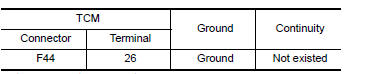
Is the inspection result normal?
YES >> Check intermittent incident. Refer to GI "Intermittent Incident".
NO >> Repair or replace malfunctioning parts.
 P099C Shift solenoid G
Other materials:
Servicing air conditioner
The air conditioner system in your NISSAN vehicle
is charged with a refrigerant designed with
the environment in mind.
This refrigerant does not harm the earth's
ozone layer.
Special charging equipment and lubricant is required
when servicing your NISSAN air conditioner.
Using improper ...
Air cleaner
WARNING
Operating the engine with the air
cleaner filter off can cause you or others
to be burned. The air cleaner filter not
only cleans the intake air, it also stops
the flame if the engine backfires. If the
air cleaner is not installed and the engine
backfires, you could be burn ...
Categories
- Manuals Home
- Nissan Versa Owners Manual
- Nissan Versa Service Manual
- Video Guides
- Questions & Answers
- External Resources
- Latest Updates
- Most Popular
- Sitemap
- Search the site
- Privacy Policy
- Contact Us

0.0054