Nissan Versa (N17): B2622 Inside antenna
DTC Logic
DTC DETECTION LOGIC 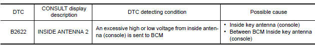
DTC CONFIRMATION PROCEDURE
1.PERFORM DTC CONFIRMATION PROCEDURE
- Select INTELLIGENT KEY of BCM using CONSULT.
- Select INSIDE ANT DIAGNOSIS in WORK SUPPORT mode.
- Perform inside key antenna (INSIDE ANT DIAGNOSIS) on WORK SUPPORT of INTELLIGENT KEY.
- Check BCM for DTC.
Is inside key antenna DTC detected?
YES >> Refer to DLK "Diagnosis Procedure".
NO >> Inside key antenna (console) is OK.
Diagnosis Procedure
Regarding Wiring Diagram information, refer to DLK "INTELLIGENT KEY SYSTEM : Wiring Diagram".
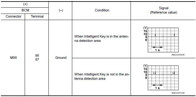
1.CHECK INSIDE KEY ANTENNA INPUT SIGNAL 1
- Turn ignition switch ON.
- Check signal between BCM harness connector and ground using
oscilloscope.
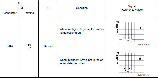
Is the inspection result normal?
YES >> Replace BCM. Refer to BCS "Removal and Installation".
NO >> GO TO 2.
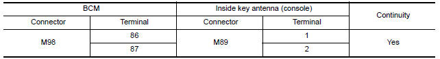
2.CHECK INSIDE KEY ANTENNA CIRCUIT
- Turn ignition switch OFF.
- Disconnect BCM connector and inside key antenna (console) connector.
- Check continuity between BCM harness connector and inside key antenna
(console) harness connector
- Check continuity between BCM harness connector and ground.
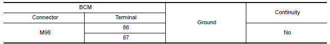
Is the inspection result normal?
YES >> GO TO 3.
NO >> Repair or replace harness.
3.CHECK INSIDE KEY ANTENNA INPUT SIGNAL 2
- Replace inside key antenna (console). (New antenna or other antenna)
- Connect BCM connector and inside key antenna (console) connector.
- Turn ignition switch ON.
- Check signal between BCM harness connector and ground using
oscilloscope.
Is the inspection result normal?
YES >> Replace inside key antenna (console).
NO >> Replace BCM. Refer to BCS "Removal and Installation".
 B2621 Inside antenna
Other materials:
Air cleaner
WARNING
Operating the engine with the air
cleaner filter off can cause you or others
to be burned. The air cleaner filter not
only cleans the intake air, it also stops
the flame if the engine backfires. If the
air cleaner is not installed and the engine
backfires, you could be burn ...
P0712 Transmission fluid temperature
sensor A
DTC Logic
DTC DETECTION LOGIC
DTC
Trouble diagnosis name
DTC detection condition
Possible causes
P0712
Transmission Fluid Temperature
Sensor "A" Circuit Low
Under the following diagnosis
conditions, the A/T fluid temperature
identified by TCM is
180C (3 ...
Categories
- Manuals Home
- Nissan Versa Owners Manual
- Nissan Versa Service Manual
- Video Guides
- Questions & Answers
- External Resources
- Latest Updates
- Most Popular
- Sitemap
- Search the site
- Privacy Policy
- Contact Us

0.0057