Nissan Versa (N17): B2628 Outside antenna
DTC Logic
DTC DETECTION LOGIC 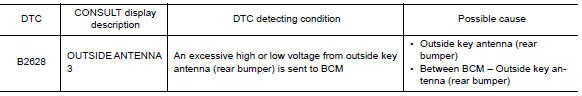
DTC CONFIRMATION PROCEDURE
1.PERFORM DTC CONFIRMATION PROCEDURE
- Turn ignition switch ON.
- Check Self Diagnostic Result mode of BCM using CONSULT.
Is outside key antenna DTC detected?
YES >> Refer to DLK "Diagnosis Procedure".
NO >> Outside key antenna (rear bumper) is OK.
Diagnosis Procedure
Regarding Wiring Diagram information, refer to DLK "INTELLIGENT KEY SYSTEM : Wiring Diagram".
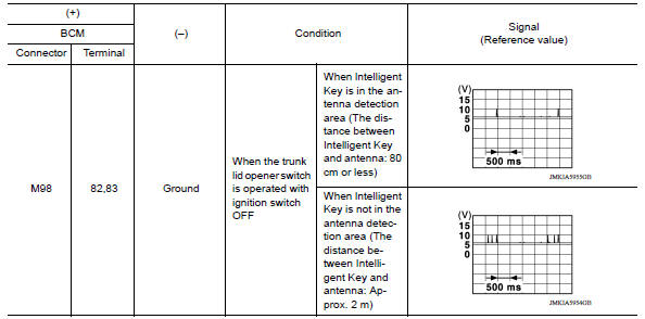
1.CHECK OUTSIDE KEY ANTENNA INPUT SIGNAL 1
- Turn ignition switch ON.
- Check signal between BCM harness connector and ground using
oscilloscope.
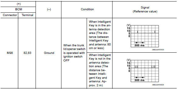
Is the inspection result normal?
YES >> Replace BCM. Refer to BCS "Removal and Installation".
NO >> GO TO 2.
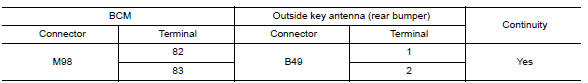
2.CHECK OUTSIDE KEY ANTENNA CIRCUIT
- Turn ignition switch OFF.
- Disconnect BCM connector and outside key antenna (rear bumper) connector.
- Check continuity between BCM harness connector and outside key antenna
(rear bumper) harness connector.
- Check continuity between BCM harness connector and ground.
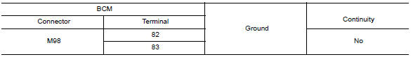
Is the inspection result normal?
YES >> GO TO 3.
NO >> Repair or replace harness.
3.CHECK OUTSIDE KEY ANTENNA INPUT SIGNAL 2
- Replace outside key antenna (rear bumper). (New antenna or other antenna)
- Connect BCM and outside key antenna (rear bumper) connector.
- Turn ignition switch ON.
- Check signal between BCM harness connector and ground using
oscilloscope.
Is the inspection result normal?
YES >> Replace outside key antenna (rear bumper).
NO >> Replace BCM. Refer to BCS "Removal and Installation".
 B2627 Outside antenna
Power supply and ground circuit
Diagnosis Procedure Regarding Wiring Diagram information, refer to BCS "Wiring Diagram". 1.CHECK FUSES AND FUSIBLE LINK Check that the following fuses and fusible link are not blown.&nb ...
Other materials:
Power supply and ground circuit
Diagnosis Procedure
1.CHECK GROUND CONNECTION
Turn ignition switch OFF.
Check ground connection E. Refer to Ground Inspection in GI, "Circuit
Inspection".
Is the inspection result normal?
YES >> GO TO 2.
NO >> Repair or replace ground connection.
2.CHECK ECM G ...
Output speed sensor
Exploded View
1. Transaxle assembly 2. Output speed sensor 3. O-ring
Front Genuine
NISSAN CVT Fluid NS-3
Removal and Installation
REMOVAL
Disconnect the harness connector from output speed sensor.
NOTE:
Lift up the vehicle and perform the work from rear of the transaxle
asse ...
Categories
- Manuals Home
- Nissan Versa Owners Manual
- Nissan Versa Service Manual
- Video Guides
- Questions & Answers
- External Resources
- Latest Updates
- Most Popular
- Sitemap
- Search the site
- Privacy Policy
- Contact Us

0.0066