 Nissan Versa Sedan Service ManualEngine » Engine control system (EC) » P0300, P0301, P0302, P0303, P0304 misfire
Diagnosis Procedure
Diagnosis Procedure
1.CHECK FOR INTAKE AIR LEAK AND PCV HOSE
- Start engine and run it at idle speed.
- Listen for the sound of the intake air leak.
- Check PCV hose connection.
Is intake air leak detected?
YES >> Discover air leak location and repair.
NO >> GO TO 2.
2.CHECK FOR EXHAUST SYSTEM CLOGGING
Stop engine and visually check exhaust tube, three way catalyst and muffler for dents.
Is the inspection result normal?
YES1 >> With CONSULT: GO TO 3.
YES2 >> Without CONSULT: GO TO 4.
NO >> Repair or replace it.
3.PERFORM POWER BALANCE TEST
With CONSULT
- Start engine.
- Perform "POWER BALANCE" in "ACTIVE TEST" mode with CONSULT.
- Make sure that each circuit produces a momentary engine speed drop.
Is the inspection result normal?
YES >> GO TO 9.
NO >> GO TO 4.
4.CHECK FUNCTION OF FUEL INJECTOR
- Start engine and let engine idle.
- Listen to each fuel injector operating sound.
Clicking noise should be heard.
Is the inspection result normal?
YES >> GO TO 5.
NO >> Perform trouble diagnosis for FUEL INJECTOR. Refer to EC, "Component Function Check".
5.CHECK FUNCTION OF IGNITION COILI
CAUTION: Do the following procedure in the place where ventilation is good without the combustible.
- Turn ignition switch OFF.
- Remove fuel pump fuse in IPDM E/R to release fuel pressure.
NOTE: Do not use CONSULT to release fuel pressure, or fuel pressure applies again during the following procedure.
- Start engine.
- After engine stalls, crank it two or three times to release all fuel pressure.
- Turn ignition switch OFF.
- Remove all ignition coil harness connectors to avoid the electrical discharge from the ignition coils.
- Remove ignition coil and spark plug of the cylinder to be checked.
- Crank engine for 5 seconds or more to remove combustion gas in the cylinder.
- Connect spark plug and harness connector to ignition coil.
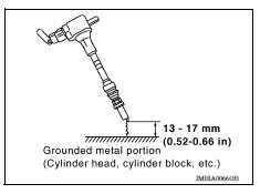
- Fix ignition coil using a rope etc. with gap of 13 17 mm (0.52 0.66 in) between the edge of the spark plug and grounded metal portion as shown in the figure.
- Crank engine for about 3 seconds, and check whether spark is generated between the spark plug and the grounded metal portion.
Spark should be generated.
CAUTION:
- Do not approach to the spark plug and the ignition coil within 50 cm (19.7 in). Be careful not to get an electrical shock while checking, because the electrical discharge voltage becomes 20 kV or more.
- It might cause to damage the ignition coil if the gap of more than 17 mm (0.66 in) is taken.
NOTE: When the gap is less than 13 mm (0.52 in), the spark might be generated even if the coil is malfunctioning.
Is the inspection result normal?
YES >> GO TO 9.
NO >> GO TO 6.
6.CHECK FUNCTION OF IGNITION COILII
- Turn ignition switch OFF.
- Disconnect spark plug and connect a knowngood spark plug.
- Crank engine for about 3 seconds, and recheck whether spark is generated between the spark plug and the grounded metal portion.
Spark should be generated.
Is the inspection result normal?
YES >> GO TO 7.
NO >> Check ignition coil, power transistor and their circuits. Refer to EC, "Component Function Check".
7.CHECK SPARK PLUG
Check the initial spark plug for fouling, etc.
Is the inspection result normal?
YES >> Replace spark plug(s) with standard type one(s). For spark plug type, refer to EM, "Spark Plug".
NO >> Repair or clean spark plug. Then GO TO 8.
8.CHECK FUNCTION OF IGNITION COILIII
- Reconnect the initial spark plugs.
- Crank engine for about 3 seconds, and recheck whether spark is generated between the spark plug and the grounded portion.
Spark should be generated.
Is the inspection result normal?
YES >> INSPECTION END
NO >> Replace spark plug(s) with standard type one(s). For spark plug type, refer to EM, "Spark Plug".
9.CHECK COMPRESSION PRESSURE
Check compression pressure. Refer to EM, "Inspection".
Is the inspection result normal?
YES >> GO TO 10.
NO >> Check pistons, piston rings, valves, valve seats and cylinder head gaskets.
10.CHECK FUEL PRESSURE
- Install all removed parts.
- Release fuel pressure to zero. Refer to EC, "Work Procedure".
- Install fuel pressure gauge and check fuel pressure. Refer to EC, "Work Procedure".
At idling: Approximately 350 kPa (3.57 kg/cm2, 51 psi)
Is the inspection result normal?
YES >> GO TO 12.
NO >> GO TO 11.
11.DETECT MALFUNCTIONING PART
Check fuel hoses and fuel tubes for clogging.
Is the inspection result normal?
YES >> Replace "fuel filter and fuel pump assembly". Refer to FL, "Removal and Installation".
NO >> Repair or replace.
12.CHECK IGNITION TIMING
Check the following items.
For procedure, refer to EC, "Inspection".
For specification, refer to EC, "Ignition Timing".
Is the inspection result normal?
YES >> GO TO 13.
NO >> Follow the EC, "Work Procedure".
13.CHECK A/F SENSOR 1 INPUT SIGNAL CIRCUIT FOR OPEN AND SHORT
- Turn ignition switch OFF.
- Disconnect A/F sensor 1 harness connector.
- Disconnect ECM harness connector.
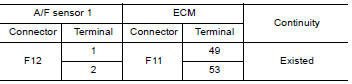
- Check the continuity between A/F sensor 1 harness connector and ECM
harness connector.
5. Check the continuity between A/F
sensor 1 harness connector or ECM harness connector and ground.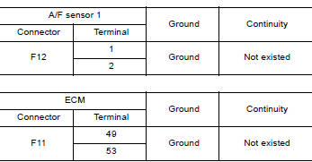
6. Also check harness for short to power.
Is the inspection result normal?
YES >> GO TO 14.
NO >> Repair open circuit or short to ground or short to power in harness or connectors.
14.CHECK A/F SENSOR 1 HEATER
Refer to EC, "Component Inspection".
Is the inspection result normal?
YES >> GO TO 15.
NO >> Replace A/F sensor 1. Refer to EM, "Exploded View".
15.CHECK MASS AIR FLOW SENSOR
With CONSULT
0.8 4.0 g/s : at idling
2.0 10.0 g/s : at 2,500 rpm
Check "MASS AIRFLOW" in "DATA MONITOR" mode with CONSULT.
With GST
0.8 4.0 g/s : at idling
2.0 10.0 g/s : at 2,500 rpm
Check mass air flow sensor signal in Service $01 with GST.
Is the measurement value within the specification?
YES >> GO TO 16.
NO >> Check connectors for rusted terminals or loose connections in the mass air flow sensor circuit or ground. Refer to EC, "DTC Logic".
16.CHECK SYMPTOM TABLE
Check items on the rough idle symptom in EC, "Symptom Table".
Is the inspection result normal?
YES >> GO TO 17.
NO >> Repair or replace.
17.ERASE THE 1ST TRIP DTC
Some tests may cause a 1st trip DTC to be set.
Erase the 1st trip DTC from the ECM memory after performing the tests.
>> GO TO 18.
18.CHECK INTERMITTENT INCIDENT
Refer to GI, "Intermittent Incident".
>> INSPECTION END
DTC Logic
Diagnosis Procedure
Nissan Versa Sedan Service Manual
Categories
