Nissan Versa (N17): P0327, P0328 KS
DTC Logic
DTC DETECTION LOGIC
| DTC No. | Trouble diagnosis name | DTC detecting condition | Possible cause |
| P0327 | Knock sensor circuit low input | An excessively low voltage from the sensor is sent to ECM. |
|
| P0328 | Knock sensor circuit high input | An excessively low voltage from the sensor is sent to ECM. |
DTC CONFIRMATION PROCEDURE
1.PRECONDITIONING
If DTC Confirmation Procedure has been previously conducted, always perform the following procedure before conducting the next test.
- Turn ignition switch OFF and wait at least 10 seconds.
- Turn ignition switch ON.
- Turn ignition switch OFF and wait at least 10 seconds.
TESTING CONDITION: Before performing the following procedure, confirm that battery voltage is more than 10 V at idle.
>> GO TO 2.
2.PERFORM DTC CONFIRMATION PROCEDURE
- Start engine and let it idle for at least 5 seconds.
- Check 1st trip DTC.
Is 1st trip DTC detected?
YES >> Go to EC, "Diagnosis Procedure".
NO >> INSPECTION END
Diagnosis Procedure
1.CHECK GROUND CONNECTION
- Turn ignition switch OFF.
- Check ground connection E15. Refer to Ground Inspection in GI, "Circuit Inspection".
Is the inspection result normal?
YES >> GO TO 2.
NO >> Repair or replace ground connection.
2.CHECK KNOCK SENSOR GROUND CIRCUIT FOR OPEN AND SHORT
- Disconnect knock sensor harness connector.
- Disconnect ECM harness connector.
- Check the continuity between knock sensor harness connector and ECM
harness connector.
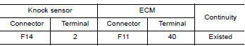
4. Also check harness for short to ground and short to power.
Is the inspection result normal?
YES >> GO TO 3.
NO >> Repair open circuit or short to ground or short to power in harness or connectors.
3.CHECK KNOCK SENSOR INPUT SIGNAL CIRCUIT FOR OPEN AND SHORT
1. Check the continuity between knock sensor
harness connector and ECM harness connector. 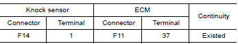
2. Also check harness for short to ground and short to power.
Is the inspection result normal?
YES >> GO TO 4.
NO >> Repair open circuit or short to ground or short to power in harness or connectors.
4.CHECK KNOCK SENSOR
Refer to EC, "Component Inspection".
Is the inspection result normal?
YES >> GO TO 5.
NO >> Replace knock sensor. Refer to EM, "Exploded View".
5.CHECK INTERMITTENT INCIDENT
Refer to GI, "Intermittent Incident".
>> INSPECTION END
Component Inspection
1.CHECK KNOCK SENSOR
- Turn ignition switch OFF.
- Disconnect knock sensor harness connector.
- Check resistance between knock sensor terminals as follows.
NOTE:
It is necessary to use an ohmmeter which can measure more than 10 MΩ. 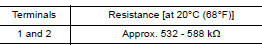
CAUTION: Do not use any knock sensors that have been dropped or physically damaged. Use only new ones.
Is the inspection result normal?
YES >> INSPECTION END
NO >> Replace knock sensor. Refer to EM, "Exploded View".
 P0300, P0301, P0302, P0303, P0304 misfire
Other materials:
Fluid cooler & fluid warmer system
FLUID COOLER & FLUID WARMER SYSTEM :
System Description
CVT FLUID COOLER SCHEMATIC
COMPONENT DESCRIPTION
CVT Oil Warmer
The CVT oil warmer (1) is installed on the front part of transaxle
assembly.
When engine is started while engine and CVT are cold, engine
coolant temperatur ...
Shift control
SHIFT CONTROL : System Description
SYSTEM DIAGRAM
DESCRIPTION
To select the gear ratio that can give the driving force to meet driver's
intent or vehicle situation, the vehicle
driving condition such as vehicle speed or accelerator pedal position is
detected and the most appropriate
g ...
Categories
- Manuals Home
- Nissan Versa Owners Manual
- Nissan Versa Service Manual
- Video Guides
- Questions & Answers
- External Resources
- Latest Updates
- Most Popular
- Sitemap
- Search the site
- Privacy Policy
- Contact Us

0.0066