Nissan Versa (N17): P1588 G Sensor
DTC Logic
DTC DETECTION LOGIC
| DTC | Trouble diagnosis name | DTC detection condition | Possible causes |
| P1588 | G Sensor Circuit Range/Performance | When the following diagnosis conditions are
satisfied and the detection conditions are satisfied
twice in the same DC: - Diagnosis condition (1 second or more) - The rate of change in G sensor detection value (mV): Between −15 and +15 inclusive - Detection condition - The rate of change in acceleration/deceleration stays +0.0273 G or more/−0.0273 or less at least for 5 seconds or more. |
G sensor |
NOTE: DC stands for "DRIVING CYCLE" and indicates a series of driving cycle of "Ignition switch OFF → ON → driving → OFF".
DTC CONFIRMATION PROCEDURE
CAUTION: Be careful of the driving speed.
1.PREPARATION BEFORE WORK
If another "DTC CONFIRMATION PROCEDURE" occurs just before, turn ignition switch OFF and wait for at least 10 seconds, then perform the next test.
>> GO TO 2.
2.CHECK DTC DETECTION
With CONSULT
- Start the engine.
- Select "Data Monitor" in "TRANSMISSION".
- Select "G SPEED".
- Drive the vehicle.
- Maintain the following conditions for 10 seconds or more.
- Stop the vehicle.
CAUTION: Never stop the engine.
- Repeat steps 4 through 6.
- Check the DTC.
Selector lever : "D" position
G SPEED : 0.05 G or more
Is "P1588" detected?
YES >> Go to TM "Diagnosis Procedure".
NO >> INSPECTION END
Diagnosis Procedure
1.CHECK G SENSOR SIGNAL
With CONSULT
- Park the vehicle on a level surface.
- Turn ignition switch ON.
- Select "Data Monitor" in "TRANSMISSION".
- Select "G SEN SLOPE".
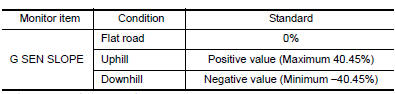
- Swing the vehicle and check if value varies between −40.45% and 40.45%.
Is the inspection result normal?
YES >> GO TO 2.
NO >> GO TO 3.
2.G SENSOR CALIBRATION (PART 1)
With CONSULT
- Select "Self Diagnostic Results" in "TRANSMISSION".
- Touch "Erase".
>> Perform "G SENSOR CALIBRATION". Refer to TM "Work Procedure".
3.CHECK G SENSOR
- Remove G sensor. TM "Removal and Installation".
- Connect the all connectors.
- Turn ignition switch ON.
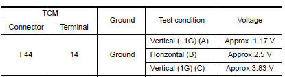
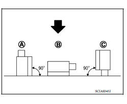
- Check voltage between TCM harness connector terminal and ground.
 : Direction of gravitational
force
: Direction of gravitational
force
Is the inspection result normal?
YES >> GO TO 4.
NO >> Replace G sensor.TM "Removal and Installation".
4.G SENSOR CALIBRATION (PART 2)
With CONSULT
- Install G sensor. TM "Removal and Installation".
- Select "Self Diagnostic Results" in "TRANSMISSION".
- Touch "Erase".
>> Perform "G SENSOR CALIBRATION". Refer to TM "Work Procedure".
 P1586 G Sensor
Other materials:
Spark plug
Exploded View
1. Ignition coil 2. Spark plug
Removal and Installation
REMOVAL
1. Remove ignition coil.
CAUTION:
Do not drop or shock ignition coil.
2. Remove spark plug using a suitable tool.
Diameter (a) : 14 mm (0.55 in)
CAUTION:
Do not drop or shock spark plug.
INSPECTION AFTER REM ...
Front stabilizer
Exploded View
1. Stabilizer bar 2. Stabilizer clamp 3. Stabilizer bushing
4. Stabilizer connecting rod 5. Strut assembly 6. Front suspension member
Front
Removal and Installation
REMOVAL
Remove wheel and tire assemblies using power tool. Refer to WT
"Adjustment".
Remove ...
Categories
- Manuals Home
- Nissan Versa Owners Manual
- Nissan Versa Service Manual
- Video Guides
- Questions & Answers
- External Resources
- Latest Updates
- Most Popular
- Sitemap
- Search the site
- Privacy Policy
- Contact Us

0.0057