Nissan Versa (N17): Front seat
DRIVER SIDE
DRIVER SIDE : Exploded View
WITH REMOVABLE HEADREST
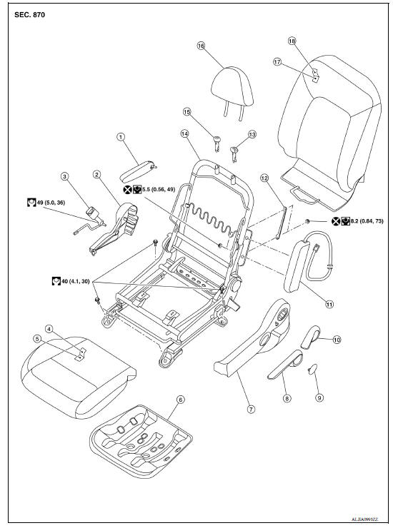
1. Armrest (if equipped) 2. Seat cushion outer finisher (RH) 3. Seat belt buckle 4. Seat cushion trim 5. Seat cushion pad 6. Seat cushion frame 7. Seat cushion outer finisher (LH) 8. Lift lever (if equipped) 9. Lift lever cap (if equipped) 10. Recline lever 11. Side air bag module 12. Chute rod 13. Headrest holder (locked) 14. Seat frame assembly 15. Headrest holder (free) 16. Headrest 17. Seatback pad 18. Seatback trim
WITHOUT REMOVABLE HEADREST
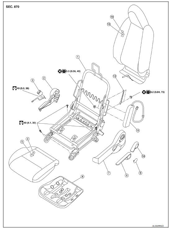
1. Seat frame assembly 2. Seat cushion outer finisher (RH) 3. Seat belt buckle 4. Seat cushion trim 5. Seat cushion pad 6. Seat cushion frame 7. Seat cushion outer finisher (LH) 8. Lift lever (if equipped) 9. Lift lever cap (if equipped) 10. Recline lever 11. Side air bag module 12. Chute rod 13. Seatback pad 14. Seatback trim
DRIVER SIDE : Removal and Installation
REMOVAL
WARNING:
Do not leave any objects (screwdrivers, tools, etc.) on the seat during seat repair. It can lead to personal injury if the side air bag module should accidentally deploy.
CAUTION:
- When removing or installing the seat trim, handle it carefully to keep dirt out and to avoid damage.
- When checking the power seat circuit for continuity using a circuit tester, do not confuse its connector with the side air bag module connector. Such an error may cause the air bag module to deploy.
- Do not drop, tilt, or bump the side air bag module while installing the seat. Always handle it with care.
- After the front side air bag module inflates, the front seatback assembly must be replaced.
- When removing and installing the seat, use shop cloths to protect components from damage.
- Before removing the front seat, turn the ignition switch OFF, disconnect both battery cables and wait at least three minutes.
- Disconnect the negative and positive battery terminals and wait at least three minutes. Refer to PG "Removal and Installation".
- Slide the seat to the full forward position.
- Remove the two rear seat bolts.
- Slide the seat to the full rearward position.
- Remove the two front seat bolts.
- Tilt the seat rearward to disconnect the harness connectors from the seat and remove.
INSTALLATION
Installation is in the reverse order of removal.
CAUTION: Make sure that the seat harness or the floor trim is not damaged during installation.
NOTE: When installing the LH front seat, tighten the bolts in the order shown.
LH front seat bolt torque : 40 Nm (4.1 kg-m, 30 ft-lb)
 Squeak and rattle trouble diagnoses
Passenger side
PASSENGER SIDE : Exploded View WITH REMOVABLE HEADREST 1. Seatback trim 2. Seatback pad 3. Headrest 4. Headrest holder (free) 5. Headrest holder (locked) 6. Chute rod 7. Seat frame assembly 8. ...
Other materials:
P1715 Input speed sensor
Description
ECM receives input speed sensor signal from TCM via the CAN communication
line. ECM uses this signal for
engine control.
DTC Logic
DTC DETECTION LOGIC
NOTE:
If DTC P1715 is displayed with DTC UXXXX, first perform the
trouble diagnosis for DTC UXXXX.
If DTC P1715 is displa ...
P074B Unable to engage 3GR
Description
This malfunction is detected when the A/T does not shift into 3GR position as
instructed by TCM. This is not
only caused by electrical malfunction (circuits open or shorted) but by
mechanical malfunction such as control
valve sticking, improper solenoid valve operation, etc.
DTC ...
Categories
- Manuals Home
- Nissan Versa Owners Manual
- Nissan Versa Service Manual
- Video Guides
- Questions & Answers
- External Resources
- Latest Updates
- Most Popular
- Sitemap
- Search the site
- Privacy Policy
- Contact Us

0.007