Nissan Versa (N17): G Sensor
Exploded View
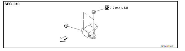
1. G sensor
![]() Front
Front
Removal and Installation
CAUTION:
- Do not drop or strike G sensor, because it may be damaged by impact.
- Do not use a power tool.
REMOVAL
- Disconnect the battery negative terminal. Refer to PG "Removal and Installation".
- Remove center console. Refer to IP "Removal and Installation".
- Disconnect the harness connector from G sensor.
- Remove G sensor.
INSTALLATION
Installation is in the reverse order of removal.
Adjustment
ADJUSTMENT AFTER INSTALLATION
Perform "G SENSOR CALIBRATION". Refer to TM "Description".
 Air breather hose
Removal and Installation REMOVAL Remove air duct (inlet). Refer to EM "Exploded View". Remove air breather hose from transaxle assembly. INSTALLATION Installation is in the reve ...
Oil pan
Exploded View 1. Transaxle assembly 2. Oil pan gasket 3. Magnet 4. Oil pan 5. Overflow tube 6. Drain plug gasket 7. Drain plug 8. Oil pan fitting bolt Removal and Installation REMOVAL R ...
Other materials:
Rear window defroster switch
To defrost the rear window glass, start the engine
and push the rear window defroster switch on.
The rear window defroster indicator light on the
switch comes on. Push the switch again to turn
the defroster off.
The rear window defroster automatically turns off
after approximately 15 m ...
Bluetooth Hands-Free Phone System without Navigation System (Type A) (if so
equipped)
WARNING
Use a phone after stopping your vehicle
in a safe location. If you have to use a
phone while driving, exercise extreme
caution at all times so full attention may
be given to vehicle operation.
If you are unable to devote full attention
to vehicle operation while talking on
...
Categories
- Manuals Home
- Nissan Versa Owners Manual
- Nissan Versa Service Manual
- Video Guides
- Questions & Answers
- External Resources
- Latest Updates
- Most Popular
- Sitemap
- Search the site
- Privacy Policy
- Contact Us

0.0047