Nissan Versa (N17): Manual air conditioning system
MANUAL AIR CONDITIONING SYSTEM : System Diagram
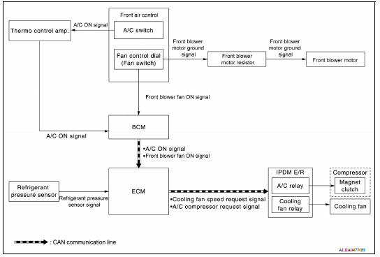
MANUAL AIR CONDITIONING SYSTEM : System Description
- The manual air conditioning system is controlled by a sequence of functions from the front air control, BCM, ECM, and IPDM E/R.
- The fan speed of the front blower motor is changed by the combination of the fan control dial (fan switch) operation and blower resistor control.
|
Module/Function |
Door control | A/C request signal | Compressor control | Cooling fan control |
| Front air control | HAC | HAC | ||
| BCM | BCS or BCS | |||
| ECM | HAC | EC | ||
| IPDM E/R | HAC | EC |
Manual air conditioning system : Compressor Control
DESCRIPTION
- When A/C switch signal is received from front air control, the thermo control amp. transmits A/C ON signal to the BCM according to evaporator fin temperature.
- When the front blower motor is operated, the front air control transmits blower fan ON signal to the BCM.
- BCM transmits the A/C ON signal and blower fan ON signal to ECM via CAN communication line. Refer to EC"CAN COMMUNICATION : System Description"
- ECM judges the conditions of each sensor (Refrigerant pressure sensor signal, accelerator position signal, etc.), and transmits the A/C compressor request signal to IPDM E/R via CAN communication line.
- By receiving the A/C compressor request signal from ECM, IPDM E/R turns the A/C relay to ON, and activates the compressor. Refer to PCS "RELAY CONTROL SYSTEM : System Description" or PCS "RELAY CONTROL SYSTEM : System Description"
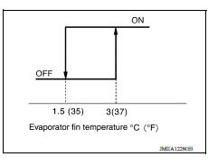
CONTROL BY THERMO CONTROL AMP.
Low Temperature Protection Control
- When thermo control amp. detects that evaporator fin temperature
is 1.5C (35F) or less, thermo control amp. switches A/C ON signal
to OFF and stops the compressor.
When the evaporator fin temperature returns to 3C (37F) or more, the compressor is activated.
CONTROL BY ECM
Refrigerant Pressure Protection
The refrigerant system is protected against excessively high- or low-pressures by the refrigerant pressure sensor, located on the liquid tank on the condenser. The refrigerant pressure sensor detects the pressure inside the refrigerant line and sends a voltage signal to the ECM. If the system pressure rises above or falls below the following values, the ECM requests the IPDM E/R to de-energize the A/C relay and disengage the compressor.
- 3.12 MPa (31.82 kg/cm2, 452.4 psi) or more (When the engine speed is less than 1,500 rpm)
- 2.74 MPa (27.95 kg/cm2, 397.3 psi) or more (When the engine speed is 1,500 rpm or more)
- 0.14 MPa (1.43 kg/cm2, 20.3 psi) or less
Compressor Oil Circulation Control
When the engine starts while the engine coolant temperature is 56C (133F) or less, ECM activates the compressor for approximately 6 seconds and circulates the compressor oil once.
Air Conditioning Cut Control
When the engine is under a high load condition, the ECM transmits an A/C relay OFF request to IPDM E/R, and stops the compressor. Refer to EC "AIR CONDITIONING CUT CONTROL : System Description".
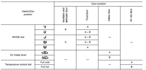
Manual air conditioning system : Door Control
SWITCHES AND THEIR CONTROL FUNCTIONS
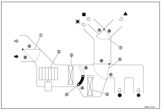
1. Intake door 2. Blower motor 3. Evaporator
4. Air mix door 5. Heater core 6. Foot door
7. Ventilator and defroster door
 Fresh air intake
  Recirculation
air
Recirculation
air  Defroster
 Center ventilator
  Side
ventilator
Side
ventilator
 Rear foot*
*: With rear foot duct
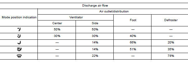
AIR DISTRIBUTION
With rear foot duct
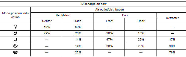
Without rear foot duct
OPERATION
Switch Name and Function
CONTROLLER
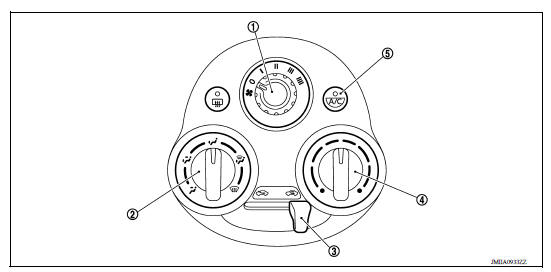
1. Fan control dial (fan switch) 2. MODE dial 3. Intake lever 4. Temperature control dial 5. A/C switch
SWITCH OPERATION
| Fan control dial (fan switch) | Fan speed can be adjusted within a range from 1st to 4th. |
| MODE dial | Mode position is selected to an optimal position by operating this dial. |
| Intake lever | The air inlet changes REC-FRE each time by operation this lever. |
| Temperature control dial | The setting temperature can be selected to an optimum temperature by operating this dial. |
| A/C switch | The compressor control (switch indicator) is turned ON-OFF each time by pressing this switch while the blower motor is activated. |
DIAGNOSIS SYSTEM (BCM) (WITH INTELLIGENT KEY SYSTEM)
COMMON ITEM
COMMON ITEM : CONSULT Function (BCM - COMMON ITEM)
APPLICATION ITEM
CONSULT performs the following functions via CAN communication with BCM.
| Direct Diagnostic Mode | Description |
| ECU identification | The BCM part number is displayed. |
| Self Diagnostic Result | The BCM self diagnostic results are displayed. |
| Data Monitor | The BCM input/output data is displayed in real time. |
| Active Test | The BCM activates outputs to test components. |
| Work support | The settings for BCM functions can be changed. |
| Configuration | - The vehicle specification can be read and saved. - The vehicle specification can be written when replacing BCM. |
| CAN DIAG SUPPORT MNTR | The result of transmit/receive diagnosis of CAN communication is displayed. |
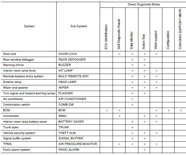
SYSTEM APPLICATION
BCM can perform the following functions.
AIR CONDITIONER
AIR CONDITIONER : CONSULT Function (BCM - AIR CONDITIONER)
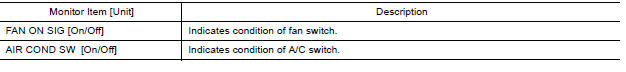
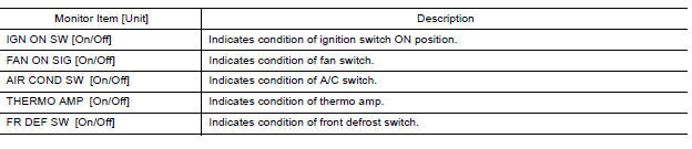
DATA MONITOR
DIAGNOSIS SYSTEM (BCM) (WITHOUT INTELLIGENT KEY SYSTEM)
COMMON ITEM
COMMON ITEM : CONSULT Function (BCM - COMMON ITEM)
APPLICATION ITEM
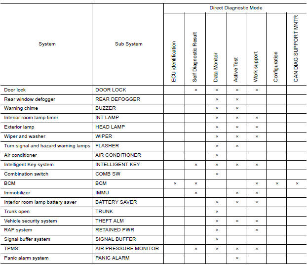
CONSULT performs the following functions via CAN communication with BCM.
| Direct Diagnostic Mode | Description |
| ECU identification | The BCM part number is displayed. |
| Self Diagnostic Result | The BCM self diagnostic results are displayed. |
| Data Monitor | The BCM input/output data is displayed in real time. |
| Active Test | The BCM activates outputs to test components. |
| Work support | The settings for BCM functions can be changed. |
| Configuration | - The vehicle specification can be read and saved. - The vehicle specification can be written when replacing BCM. |
| CAN DIAG SUPPORT MNTR | The result of transmit/receive diagnosis of CAN communication is displayed. |
SYSTEM APPLICATION
BCM can perform the following functions.
AIR CONDITIONER
AIR CONDITIONER : CONSULT Function (BCM - AIR CONDITIONER)
SYSTEM APPLICATION
ECU DIAGNOSIS INFORMATION
BCM, ECM, IPDM E/R
List of ECU Reference
| ECU | Reference |
| BCM (with Intelligent Key system) | BCS"Reference Value" |
| BCS "Fail-safe" | |
| BCS "DTC Inspection Priority Chart" | |
| BCS "DTC Index" | |
| BCM (without Intelligent Key system) | BCS "Reference Value" |
| BCS "Fail-safe" | |
| BCS "DTC Inspection Priority Chart" | |
| BCS "DTC Index" | |
| ECM | EC "Reference Value" |
| EC "Fail Safe" | |
| EC "DTC Inspection Priority Chart" | |
| EC "DTC Index" | |
| IPDM E/R (with Intelligent Key system) | PCS "Reference Value" |
| PCS "Fail-safe" | |
| PCS "DTC Index" | |
| IPDM E/R (without Intelligent Key system) | PCS "Reference Value" |
| PCS "Fail-Safe" | |
| PCS "DTC Index" |
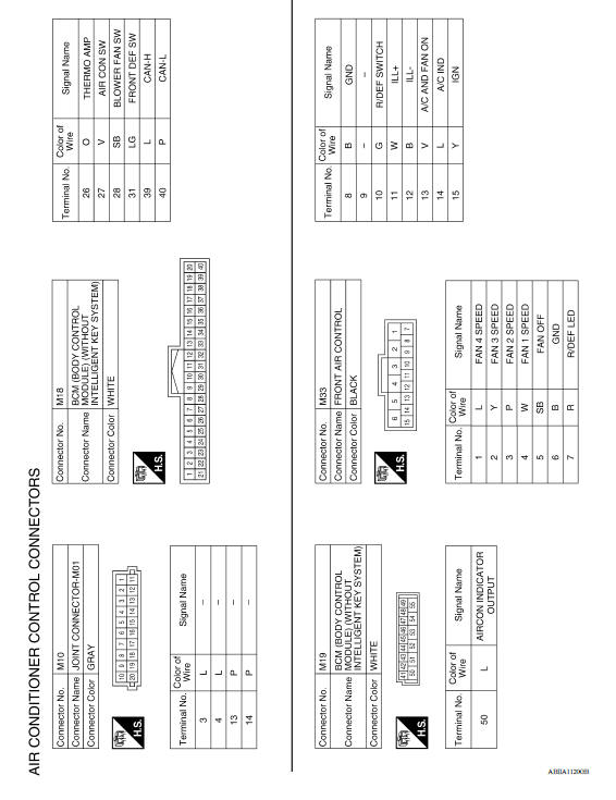
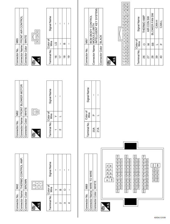
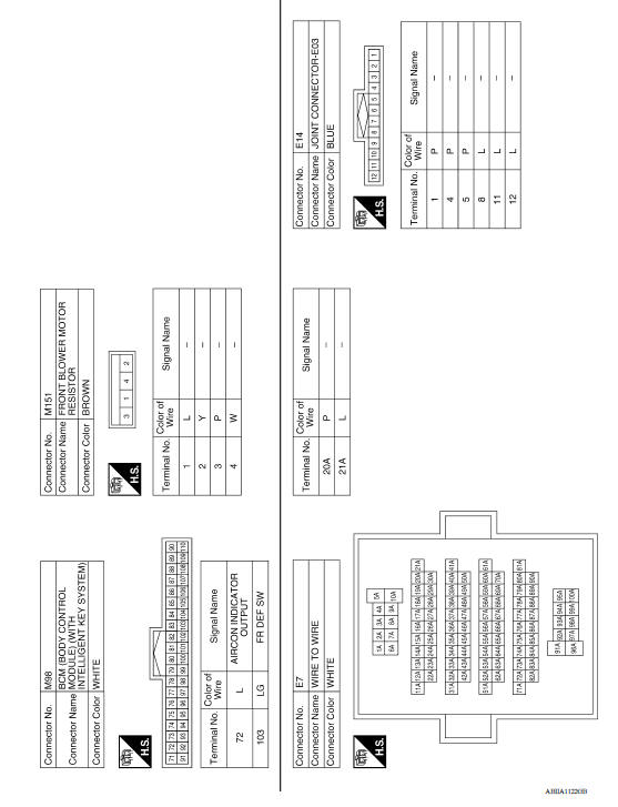
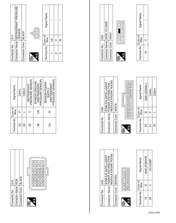
WIRING DIAGRAM
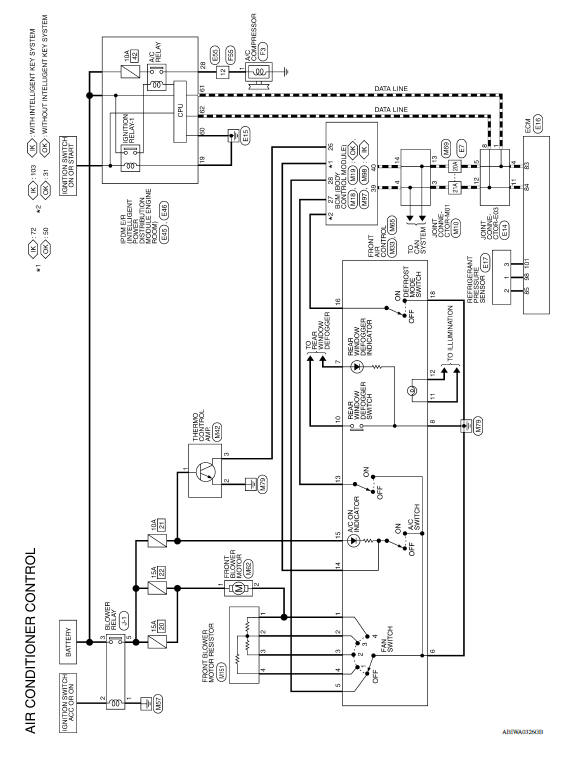
MANUAL AIR CONDITIONING SYSTEM
Wiring Diagram
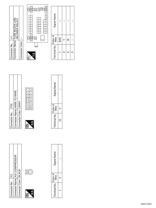
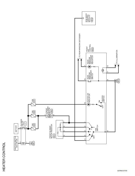
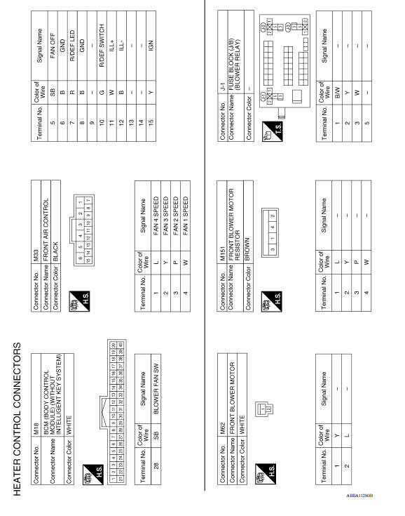
MANUAL HEATER SYSTEM
Wiring Diagram
BASIC INSPECTION
 Precautions
Diagnosis and repair workflow
Workflow OVERALL SEQUENCE DETAILED FLOW 1.INTERVIEW CUSTOMER Interview the customer to obtain as much information as possible about the conditions and environment under which the malfunctio ...
Other materials:
Spark plugs
Replacing spark plugs
Platinum-tipped spark plugs
It is not necessary to replace platinum-tipped A
spark plugs as frequently as conventional type
spark plugs because they last much longer. Follow
the maintenance log shown in the Maintenance
and Schedules section of this manual. Do
not ser ...
Uniform tire quality grading
DOT (Department of Transportation) Quality
Grades: All passenger car tires must conform to
federal safety requirements in addition to these
grades.
Quality grades can be found where applicable on
the tire sidewall between tread shoulder and
maximum section width. For example:
Treadwear 200 ...
Categories
- Manuals Home
- Nissan Versa Owners Manual
- Nissan Versa Service Manual
- Video Guides
- Questions & Answers
- External Resources
- Latest Updates
- Most Popular
- Sitemap
- Search the site
- Privacy Policy
- Contact Us

0.0052