Nissan Versa (N17): U1000 CAN COMM
DTC Logic
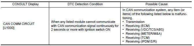
DTC DETECTION LOGIC
NOTE: U1000 can be set if a module harness was disconnected and
reconnected, perhaps during a repair. Confirm that there are actual CAN
diagnostic symptoms and a present DTC by performing the Self Diagnostic Result
procedure.
Diagnosis Procedure
1. PERFORM SELF DIAGNOSTIC RESULT
- Turn ignition switch ON and wait for 2 second or more.
- Check "SELF- DIAG RESULTS".
Is "CAN COMM CIRCUIT" displayed?
YES >> Perform CAN Diagnosis as described in DIAGNOSIS section of CONSULT Operation manual.
NO >> Refer to GI "Intermittent Incident".
U1010 CONTROL UNIT (CAN)
DTC Logic
DTC DETECTION LOGIC 
Diagnosis Procedure
1.REPLACE BCM
When DTC "U1010" is detected, replace BCM.
>> Replace BCM. Refer to BCS "Removal and Installation".
 Diagnosis and repair workflow
Work Flow OVERALL SEQUENCE DETAILED FLOW 1.GET INFORMATION FOR SYMPTOM Get the detailed information from the customer about the symptom (the condition and the environment when the incident/ ...
Power supply and ground circuit
Diagnosis Procedure Regarding Wiring Diagram information, refer to BCS "Wiring Diagram". 1.CHECK FUSES AND FUSIBLE LINK Check that the following fuses and fusible link are not blown. ...
Other materials:
5Th main gear assembly
Removal and Installation
REMOVAL
Move the shift selector to the 3rd gear position.
Disconnect the shifter cable and the selector cable from shifter lever A
and selector lever. Refer to TM,
"Removal and Installation".
CAUTION:
Do not move shifter lever A and selector leve ...
P0732 2GR Incorrect ratio
Description
This malfunction is detected when the A/T does not shift into 2GR position as
instructed by TCM. This is not
only caused by electrical malfunction (circuits open or shorted) but by
mechanical malfunction such as control
valve sticking, improper solenoid valve operation, etc.
DTC ...
Categories
- Manuals Home
- Nissan Versa Owners Manual
- Nissan Versa Service Manual
- Video Guides
- Questions & Answers
- External Resources
- Latest Updates
- Most Popular
- Sitemap
- Search the site
- Privacy Policy
- Contact Us

0.0097