Nissan Versa (N17): ABS Branch line circuit
Diagnosis Procedure
1.CHECK CONNECTOR
1. Turn the ignition switch OFF.
2. Disconnect the battery cable from the negative terminal.
3. Check the terminals and connectors of the ABS actuator and electric unit (control unit) for damage, bend and loose connection (unit side and connector side).
Is the inspection result normal?
YES >> GO TO 2.
NO >> Repair the terminal and connector.
2.CHECK HARNESS FOR OPEN CIRCUIT
1. Disconnect the connector of ABS actuator and electric unit (control unit).
2. Check the resistance between the ABS actuator and electric unit (control
unit) harness connector terminals.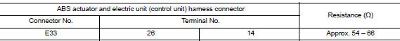
Is the measurement value within the specification?
YES >> GO TO 3.
NO >> Repair the ABS actuator and electric unit (control unit) branch line.
3.CHECK POWER SUPPLY AND GROUND CIRCUIT
Check the power supply and the ground circuit of the ABS actuator and electric unit (control unit). Refer to BRC "Diagnosis Procedure".
Is the inspection result normal?
YES (Present error)>>Replace the ABS actuator and electric unit (control unit). Refer to BRC "Removal and Installation".
YES (Past error)>>Error was detected in the ABS actuator and electric unit (control unit) branch line.
NO >> Repair the power supply and the ground circuit.
 ECM Branch line circuit
Diagnosis Procedure 1.CHECK CONNECTOR 1. Turn the ignition switch OFF. 2. Disconnect the battery cable from the negative terminal. 3. Check the terminals and connectors of the ECM for damage, bend ...
IPDM-E Branch line circuit
Diagnosis Procedure 1.CHECK CONNECTOR 1. Turn the ignition switch OFF. 2. Disconnect the battery cable from the negative terminal. 3. Check the terminals and connectors of the IPDM E/R for damage, ...
Other materials:
Exhaust system
Exploded View
1. Heated oxygen sensor 2 2. Catalyst cover (upper) 3. Seal bearing
4. Catalyst cover (lower) 5. Spring 6. Spring
7. Mounting rubber 8. Main muffler 9. Ring gasket
10. Center muffler 11. Mounting rubber 12. Seal bearing
13. Exhaust front tube
Removal and Installation
WARNIN ...
Clutch piping
Exploded View
1. CSC (Concentric Slave Cylinder) 2. Clutch tube 3. Clutch damper
4. Bracket 5. Master cylinder
Hydraulic Layout
1. Clutch tube 2. Lock pin 3. CSC (concentric slave cylinder)
4. Clutch damper 5. Master cylinder 6. Clutch pedal
Removal and Installation
CAUTION:
Do not ...
Categories
- Manuals Home
- Nissan Versa Owners Manual
- Nissan Versa Service Manual
- Video Guides
- Questions & Answers
- External Resources
- Latest Updates
- Most Popular
- Sitemap
- Search the site
- Privacy Policy
- Contact Us

0.005