Nissan Versa (N17): IPDM-E Branch line circuit
Diagnosis Procedure
1.CHECK CONNECTOR
1. Turn the ignition switch OFF.
2. Disconnect the battery cable from the negative terminal.
3. Check the terminals and connectors of the IPDM E/R for damage, bend and loose connection (unit side and connector side).
Is the inspection result normal?
YES >> GO TO 2.
NO >> Repair the terminal and connector.
2.CHECK HARNESS FOR OPEN CIRCUIT
1. Disconnect the connector of IPDM E/R.
2. Check the resistance between the IPDM E/R harness connector terminals.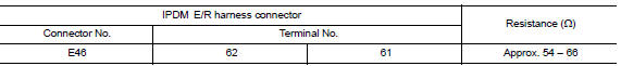
Is the measurement value within the specification?
YES >> GO TO 3.
NO >> Repair the IPDM E/R branch line.
3.CHECK POWER SUPPLY AND GROUND CIRCUIT
Check the power supply and the ground circuit of the IPDM E/R. Refer to the following.
- With Intelligent Key system: PCS"Diagnosis Procedure"
- Without Intelligent Key system: PCS "Diagnosis Procedure"
Is the inspection result normal?
YES (Present error)>>Replace the IPDM E/R. Refer to the following.
- With Intelligent Key system: PCS "Removal and Installation"
- Without Intelligent Key system: PCS "Removal and Installation"
YES (Past error)>>Error was detected in the IPDM E/R branch line.
NO >> Repair the power supply and the ground circuit.
 ABS Branch line circuit
Diagnosis Procedure 1.CHECK CONNECTOR 1. Turn the ignition switch OFF. 2. Disconnect the battery cable from the negative terminal. 3. Check the terminals and connectors of the ABS actuator and ele ...
TCM Branch line circuit
Diagnosis Procedure 1.CHECK CONNECTOR 1. Turn the ignition switch OFF. 2. Disconnect the battery cable from the negative terminal. 3. Check the following terminals and connectors for damage, bend ...
Other materials:
EVAP canister filter
Exploded View
1. EVAP canister vent control valve hose 2. Canister drain hose 3. EVAP
canister filter
Front
Removal and Installation
REMOVAL
Remove the EVAP canister protector cover.
Disconnect EVAP canister vent control valve hose from EVAP canister
filter.
Disconnect caniste ...
U0100 Lost communication (ECM A)
DTC Logic
DTC DETECTION LOGIC
DTC
Trouble diagnosis name
DTC detection condition
Possible causes
U0100
Lost Communication With
ECM/PCM "A"
When the ignition switch is ON,
TCM is unable to receive the
CAN communications signal
from ECM continuously for 2
...
Categories
- Manuals Home
- Nissan Versa Owners Manual
- Nissan Versa Service Manual
- Video Guides
- Questions & Answers
- External Resources
- Latest Updates
- Most Popular
- Sitemap
- Search the site
- Privacy Policy
- Contact Us

0.0061