Toyota
Nissan Versa
 Sedan Service Manual
Transmission & driveline » Transaxle & transmission (TM)
Additional service when replacing transaxle assembly

Description

Perform the following work after the transaxle assembly is replaced.

ERASING AND LOADING OF THE CALIBRATION DATA

  • The TCM acquires calibration data (individual characteristic value) of each solenoid that is stored in the ROM assembly (in the control valve). This enables the TCM to perform accurate control. For this reason, after the transaxle assembly is replaced, it is necessary to erase the calibration data that is stored in the TCM and load new calibration data.

    ERASING THE LEARNED VALUE DATA

  • TCM learns indicated pressure for appropriate control of the transaxle assembly and records the learned values. For this reason, the leaned values stored in TCM must be erased after replacing a transaxle assembly.

Work Procedure

1.INITIALIZE TCM

With CONSULT

  1. Set parking brake.
  2. Turn ignition switch ON.
  3. Select "Work Support" in "TRANSMISSION".
  4. Select "ERASE MEMORY DATA".
  5. While maintaining the conditions below, touch "Start".
  • Vehicle stop status
  • With engine stopped
  • Selector lever: "R" position
  • Accelerator pedal: Depressed

NOTE: Select "Start" and complete within approximately 20 seconds.

Is "COMPLETED" displayed?

YES >> GO TO 2.

NO >> Turn ignition switch OFF and wait for a minimum of 20 seconds then perform the work again.

2.CHECK AFTER TCM IS INITIALIZED

With CONSULT

  1. Turn ignition switch OFF with the selector lever in "R" position and wait for 20 seconds or more.
  2. Turn ignition switch ON with the selector lever in "R" position.

CAUTION: Never start the engine.

  1. Select "CALIB DATA" in "TRANSMISSION".
  2. Check that indicated value of "CALIB DATA" is equal to the value shown in the following table. 

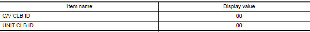
Is the indicated value of "CALIB DATA" equal to the value shown in the table?

YES >> GO TO 3.

NO >> GO TO 1.

3.CHECK LOADING OF CALIBRATION DATA

  1. Shift the selector lever to the "P" position.
  2. Check that "P" is displayed on shift position indicator on combination meter.

NOTE: Displayed approximately 5 seconds after the selector lever is moved to the "P" position.

Does shift position indicator display "P"?

YES >> WORK END

NO >> GO TO 4.

4.DETECT MALFUNCTION ITEMS

Check the following items:

  • Harness between the TCM and the ROM assembly inside the transaxle assembly is open or shorted.
  • Disconnected, loose, bent, collapsed, or otherwise abnormal connector housing terminals

Is the inspection result normal?

YES >> GO TO 1.

NO >> Repair or replace the malfunctioning parts.

    More about «Transaxle & transmission (TM)»:

    Precautions

    Structure and operation

    Position switch

    Gear oil

    Side oil seal

    Position switch

    Control linkage

    Air breather hose

    5Th main gear assembly

    Transaxle assembly

    Transaxle assembly

    Input shaft and gear

    Mainshaft and gear

    Final drive

    Precautions

    A/T Control system

    A/T Shift lock system

    Transaxle

    A/T control system

    Line pressure control

    Shift change control

    Lock-up control

    Diagnosis description

    Consult function

    TCM

    Diagnosis and repair work flow

    Additional service when replacing TCM

    Additional service when replacing transaxle assembly

    A/T Fluid cooler

    Stall test

    Line pressure test

    U0073 Communication bus a off

    U0100 Lost communication (ECM A)

    U0140 Lost communication (BCM)

    U0155 Lost communication (IPC)

    U0300 Can communication data

    U1000 Can comm circuit

    U1117 Lost communication (ABS)

    P062F EEPROM

    P0705 Transmission range switch A

    P0706 Transmission range sensor A

    P0711 Transmission fluid temperature sensor A

    P0712 Transmission fluid temperature sensor A

    P0713 Transmission fluid temperature sensor A

    P0717 Input speed sensor A

    P0720 Output speed sensor

    P072C Stuck in 1GR

    P072D Stuck in 2GR

    P072E Stuck in 3GR

    P072F Stuck in 4GR

    P0731 1GR Incorrect ratio

    P0732 2GR Incorrect ratio

    P0733 3GR Incorrect ratio

    P0734 4GR Incorrect ratio

    P073E Unable to engage r range

    P073F Unable to engage 1GR

    P0740 Torque converter

    P0743 Torque converter

    P0744 Torque converter

    P074A Unable to engage 2GR

    P074B Unable to engage 3GR

    P074C Unable to engage 4GR

    P0863 TCM Communication

    P0890 TCM

    P0962 Pressure control solenoid A

    P0963 Pressure control solenoid A

    P0973 Shift solenoid A

    P0974 Shift solenoid A

    P0976 Shift solenoid B

    P0977 Shift solenoid B

    P0979 Shift solenoid C

    P0980 Shift solenoid C

    P0982 Shift solenoid D

    P0983 Shift solenoid D

    P2760 Torque converter

    Main power supply and ground circuit

    Overdrive control switch

    O/D OFF indicator lamp

    Shift position indicator circuit

    Shift lock system

    A/T Fluid

    A/T Shift selector

    Control cable

    Key interlock cable

    TCM

    Oil pan

    Output speed sensor

    Differential side oil seal

    Fluid cooler tube

    Transmission assembly

    Service data and specifications (SDS)

    Precautions

    Component parts

    Shift lock system

    Structure and operation

    Fluid cooler & fluid warmer system

    CVT Control system

    Line pressure control

    Shift control

    Lock-up control

    Idle neutral control

    Diagnosis system (TCM)

    TCM

    Diagnosis and repair work flow

    Additional service when replacing TCM

    Additional service when replacing transaxle assembly

    Calibration of G Sensor

    CVT Fluid cooler system

    Stall test

    Line pressure test

    U0073 Communication bus A off

    U0100 Lost communication (ECM A)

    U0140 Lost communication (BCM)

    U0141 Lost communication (BCM A)

    U0155 Lost communication (IPC)

    U0300 Can communication data

    U1000 Can COMM circuit

    U1117 Lost communication (ABS)

    P062F EEPROM

    P0705 Transmission range sensor A

    P0706 Transmission range sensor A

    P0711 Transmission fluid temperature sensor A

    P0712 Transmission fluid temperature sensor A

    P0713 Transmission fluid temperature sensor A

    P0715  Input speed sensor A

    P0720 Output speed sensor

    P0740 Torque converter

    P0743 Torque converter

    P0744 Torque converter

    P0746 Pressure control solenoid A

    P0846 Transmission fluid pressure SEN/SW B

    P0847 Transmission fluid pressure SEN/SW B

    P0848 Transmission fluid pressure SEN/SW B

    P0863 TCM Communication

    P0890 TCM

    P0962 Pressure control solenoid A

    P0963 Pressure control solenoid A

    P0965 Pressure control solenoid B

    P0966 Pressure control solenoid B

    P0967 Pressure control solenoid B

    P0998 Shift solenoid F

    P0999 Shift solenoid F

    P099B Shift solenoid G

    P099C Shift solenoid G

    P1586 G Sensor

    P1588 G Sensor

    P2765 Clutch B speed sensor

    P2857 Clutch A pressure

    P2858 Clutch B pressure

    P2859 Clutch A pressure

    P285A Clutch B pressure

    Main power supply and ground circuit

    Overdrive control switch

    OD OFF indicator lamp

    Shift position indicator circuit

    Shift lock system

    CVT Control system

    CVT Fluid

    CVT Shift selector

    Control cable

    Key interlock cable

    TCM

    Air breather hose

    G Sensor

    Oil pan

    Primary speed sensor

    Secondary speed sensor

    Output speed sensor

    Differential side oil seal

    Water hose

    Fluid cooler hose

    PLUG

    Transmission assembly

    Service data and specifications (SDS)

    Nissan Versa Sedan Service Manual / Transmission & driveline / Transaxle & transmission (TM) / Additional service when replacing transaxle assembly

    Nissan Versa Sedan Service Manual

    Categories


    © 2017-2024 Copyright www.niveguide.com