Nissan Versa (N17): Automatic speed control device (ASCD)
Automatic speed control device (ascd) : switch name and function
SWITCHES AND INDICATORS
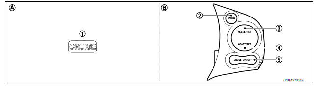
1. CRUISE indicator 2. CANCEL switch 3. ACCEL/RES switch 4. COAST/SET switch 5. ASCD MAIN switch A. On the combination meter B. On the steering wheel
SET SPEED RANGE
ASCD system can be set the following vehicle speed.
| Minimum speed (Approx.) | Maximum speed (Approx.) |
| 38 km/h (24 MPH) | 144 km/h (90 MPH) |
SWITCH OPERATION
| Item | Function |
| CANCEL switch | Cancels the cruise control driving. |
| ACCEL/RES switch |
|
| COAST/SET switch |
|
| ASCD MAIN switch | Master switch to activate the ASCD system. |
SET OPERATION
Press MAIN switch. (The CRUISE indicator in combination meter illuminates.) When vehicle speed reaches a desired speed between approximately 38 km/h (24 MPH) and 144 km/h (90 MPH), press COAST/SET switch.
ACCELERATE OPERATION
If the ACCEL/RES switch is pressed during the cruise control driving, increase the vehicle speed until the switch is released or vehicle speed reaches maximum speed controlled by the system.
And then ASCD will keep the new set speed.
CANCEL OPERATION
- When any of following conditions exist, the cruise operation is canceled.
- CANCEL switch is pressed
- ASCD MAIN switch is pressed (Set speed is cleared)
- More than 2 switches at ASCD steering switch are pressed at the same time (Set speed is cleared)
- Brake pedal is depressed
- Selector lever is changed to N, P or R position
- Vehicle speed decreased to 13 km/h (8 MPH) lower than the set speed
- TCS system is operated
- When the ECM detects any of the following conditions, the ECM cancels the cruise operation and informs the driver by blinking CRUISE indicator lamp.
- Engine coolant temperature is slightly higher than the normal operating temperature, CRUISE indicator lamp is blinked slowly.
NOTE: Engine coolant temperature decreases to the normal operating temperature, CRUISE indicator lamp stop blinking and the cruise operation is able to work.
- Malfunction for some selfdiagnoses regarding ASCD control: CRUISE indicator will blink quickly.
- When ASCD MAIN switch is turned to OFF during the cruise control driving, all of ASCD operations is canceled and vehicle speed memory is erased.
COAST OPERATION
When the COAST/SET switch is pressed during the cruise control driving, decrease vehicle set speed until the switch is released. And then ASCD will keep the new set speed.
RESUME OPERATION
- When the ACCEL/RES switch is pressed after the cancel operation other than pressing ASCD MAIN switch is performed, vehicle speed is return to last set speed. To resume vehicle set speed, vehicle condition must meet following conditions.
- Brake pedal is released
- Selector lever is in other than P and N positions
- Vehicle speed is greater than 38 km/h (24 MPH) and less than 144 km/h (90 MPH)
On board diagnostic (obd) system
Diagnosis Description
This system is an on board diagnostic system that records exhaust emissionrelated diagnostic information and detects a sensors/actuatorrelated malfunction. A malfunction is indicated by the malfunction indicator lamp (MIL) and stored in ECU memory as a DTC. The diagnostic information can be obtained with the diagnostic tool (GST: Generic Scan Tool).
Gst (generic scan tool)
When GST is connected with a data link connector equipped on the vehicle side, it will communicate with the control unit equipped in the vehicle and then enable various kinds of diagnostic tests.
NOTE:
Service $0A is not applied for regions where it is not mandated.
 Automatic speed control device (ASCD)
Automatic speed control device (ascd) : system diagram NOTE: Transmission range switch and TCM is also for A/T models. Automatic speed control device (ascd) : system description INPUT/OUTPUT ...

Other materials:
Uniform tire quality grading
DOT (Department of Transportation) Quality
Grades: All passenger car tires must conform to
federal safety requirements in addition to these
grades.
Quality grades can be found where applicable on
the tire sidewall between tread shoulder and
maximum section width. For example:
Treadwear 200 ...
P0507 ISC system
Description
The ECM controls the engine idle speed to a specified level through the fine
adjustment of the air, which is let
into the intake manifold, by operating the electric throttle control actuator.
The operating of the throttle valve is
varied to allow for optimum control of the engine ...
Categories
- Manuals Home
- Nissan Versa Owners Manual
- Nissan Versa Service Manual
- Video Guides
- Questions & Answers
- External Resources
- Latest Updates
- Most Popular
- Sitemap
- Search the site
- Privacy Policy
- Contact Us

0.0073