Nissan Versa (N17): Automatic speed control device (ASCD)
Automatic speed control device (ascd) : system diagram
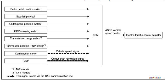
NOTE:
Transmission range switch and TCM is also for A/T models.
Automatic speed control device (ascd) : system description
INPUT/OUTPUT SIGNAL CHART
| Sensor | Input signal to ECM | ECM function | Actuator |
| Brake pedal position switch | Brake pedal operation | ASCD vehicle speed control | Electric throttle control actuator |
| Stop lamp switch | |||
| Clutch pedal position switch (M/T models) | Clutch pedal operation | ||
| ASCD steering switch | ASCD steering switch operation | ||
| Transmission range switch (A/T models or CVT models) | PNP signal | ||
| Park/neutral position (PNP) PNP signal switch (M/T models) | |||
| Combination meter | Vehicle speed signal* | ||
| TCM (A/T models or CVT models) | Output shaft revolution signal* |
*: This signal is sent to the ECM via the CAN communication line
BASIC ASCD SYSTEM
Automatic Speed Control Device (ASCD) allows a driver to keep vehicle at predetermined constant speed without depressing accelerator pedal. Driver can be set the vehicle speed in the set speed range.
ECM controls throttle angle of electric throttle control actuator to regulate engine speed.
Operation status of ASCD is indicated in combination meter.
If any malfunction occurs in the ASCD system, it automatically deactivates the ASCD control.
CAUTION:
Always drive vehicle in a safe manner according to traffic conditions and obey all traffic laws.
Alternator power generation voltage variable control system
Alternator power generation voltage variable control system : system description
The alternator power generation voltage variable control system controls the amount of power generation, according to a battery loaded condition. ECM judges a battery condition, according to a signal received from the battery current sensor which detects a charge/discharge current. ECM then transmits a signal to IPDM E/ R to command power generation via CAN communication. IPDM E/R transmits a power generation control signal to the alternator so that the system can control the amount of power generation. The voltage of power generation is lowered during battery lowload conditions and boosted under heavy load conditions. In this way, the system reduces the engine load through the adequate power generation control.
 Fuel filler cap warning system
FUEL FILLER CAP WARNING SYSTEM : System Diagram FUEL FILLER CAP WARNING SYSTEM : System Description INPUT/OUTPUT SIGNAL CHART Input Unit/Sensor Input signal to ECM ECM function ...
Automatic speed control device (ASCD)
Automatic speed control device (ascd) : switch name and function SWITCHES AND INDICATORS 1. CRUISE indicator 2. CANCEL switch 3. ACCEL/RES switch 4. COAST/SET switch 5. ASCD MAIN switch A. O ...
Other materials:
Seat belt retractor
SEAT BELT RETRACTOR : Removal and Installation
REMOVAL
CAUTION:
Before servicing, turn ignition switch OFF, disconnect battery negative terminal
and wait at least three
minutes.
Disconnect both the negative and positive battery cables, then wait at
least three minutes. Refer to PG " ...
ACC Warning does not operate
Diagnosis Procedure
1.CHECK DTC WITH BCM
Check that DTC is not detected with BCM
Is the inspection result normal?
YES >> GO TO 2.
NO >> Perform trouble diagnosis relevant to DTC indicated.
2.CHECK DTC WITH COMBINATION METER
Check that DTC is not detected with combination meter
...
Categories
- Manuals Home
- Nissan Versa Owners Manual
- Nissan Versa Service Manual
- Video Guides
- Questions & Answers
- External Resources
- Latest Updates
- Most Popular
- Sitemap
- Search the site
- Privacy Policy
- Contact Us

0.0063