Nissan Versa (N17): Oil cooler
Exploded View
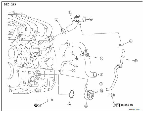
1. Radiator hose (upper) 2. Hose clamp 3. Radiator hose (lower) 4. Hose clamp 5. Water hose 6. Oil cooler 7. Connector bolt 8. Water hose 9. Oring A. To radiator (upper side) B. To radiator (lower side) 10. Relief valve
Removal and Installation
REMOVAL
NOTE:
When removing components such as hoses, tubes/lines, etc., cap or plug openings to prevent fluid from spilling.
- Remove the engine under cover.
- Drain engine oil.
- Drain engine coolant. CAUTION: Perform when engine is cold.
- Remove oil filter.
- Remove water hoses from the oil cooler.
- Remove oil cooler and Oring.
CAUTION: Do not reuse Orings.
INSPECTION AFTER REMOVAL
Oil Cooler Check oil cooler for cracks. Check oil cooler for clogging by blowing compressed air through engine coolant inlet. If necessary, replace oil cooler assembly.
Relief Valve Inspect relief valve for movement, cracks and breaks by pushing the ball. If replacement is necessary, remove the valve by prying it out using a suitable tool. Install a new valve by tapping it in place.
INSTALLATION
Installation is in the reverse order of removal.
- Ensure that no foreign objects are adhering to the sealing surfaces of the oil cooler and oil pan (upper).
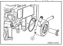
- Tighten connector bolt after aligning cutout (1) on oil cooler with protrusion (2) on oil pan (upper) side.
CAUTION:
- Do not reuse Oring.
- Replace relief valve if removed.
INSPECTION AFTER INSTALLATION
- Before starting engine, check oil/fluid levels, including engine coolant and engine oil. If less than required quantity, fill to the specified level.
- Use procedure below to check for fuel leakage.
- Turn ignition switch ON (with engine stopped). With fuel pressure applied to fuel piping, check for fuel leakage at connection points.
- Start engine. With engine speed increased, check again for fuel leakage at connection points.
- Run engine to check for unusual noise and vibration.
NOTE:
If hydraulic pressure inside timing chain tensioner drops after removal and installation, slack in the guide may generate a pounding noise during and just after engine start. However, this is normal. Noise will stop after hydraulic pressure rises.
- Warm up engine thoroughly to make sure there is no leakage of fuel, exhaust gas, or any oils/fluids including engine oil and engine coolant.
- Bleed air from passages in lines and hoses, such as in cooling system.
- After cooling down engine, again check oil/fluid levels, including engine oil and engine coolant. Refill to specified level, if necessary.
- Summary of the inspection items:
| Item | Before starting engine | Engine running | After engine stopped | |
| Engine coolant | Level | Leakage | Level | |
| Engine oil | Level | Leakage | Level | |
| Transmission/ transaxle fluid | A/T and CVT Models | Leakage | Level/Leakage | Leakage |
| M/T Models | Level/Leakage | Leakage | Level/Leakage | |
| Other oils and fluids* | Level | Leakage | Level | |
| Fuel | Leakage | Leakage | Leakage | |
| Exhaust gas | Leakage | |||
*Power steering fluid, brake fluid, etc.
 Oil pump
Exploded View 1. Rear oil seal 2. Oring 3. Oil pan (upper) 4. Oil pump chain tensioner (for oil pump drive chain) 5. Oil pump drive chain 6. Crankshaft key 7. Crankshaft sprocket 8. Oil pump s ...
Service data and specifications
(SDS)
Periodical Maintenance Specification ENGINE OIL CAPACITY (APPROXIMATE) & ...
Other materials:
Air breather hose
Exploded View
1. Cap 2. Air breather hose 3. 2-way connector
Removal and Installation
REMOVAL
Remove air cleaner case. Refer to EM, "Removal and Installation".
Remove air breather hose from the 2-way connector.
CAUTION:
When removing air breather hose, be sure to hold 2- ...
Oil pan
Exploded View
1. Transaxle assembly 2. Oil pan gasket 3. Magnet
4. Oil pan 5. Overflow tube 6. Drain plug gasket
7. Drain plug 8. Oil pan fitting bolt
Removal and Installation
REMOVAL
Remove the drain plug and overflow tube, and then drain the CVT fluid.WARNING:
CVT fluid can splash ...
Categories
- Manuals Home
- Nissan Versa Owners Manual
- Nissan Versa Service Manual
- Video Guides
- Questions & Answers
- External Resources
- Latest Updates
- Most Popular
- Sitemap
- Search the site
- Privacy Policy
- Contact Us

0.0048