Nissan Versa (N17): B2098 Ignition relay on stuck
Description
The ignition relay integrated in IPDM E/R is operated with ignition switch ON signal from the ignition switch.
DTC Logic
DTC DETECTION LOGIC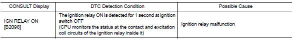
Diagnosis Procedure
1. PERFORM SELF DIAGNOSTIC RESULT
1. Turn the ignition switch ON.
2. Erase "SELF-DIAG RESULTS" of IPDM E/R.
3. Turn ignition switch OFF, and wait for 1 second or more.
4. Turn the ignition switch ON. Check "SELF-DIAG RESULTS" again.
Is "IGN RELAY ON" displayed?
YES >> Replace IPDM E/R. Refer to PCS "Removal and Installation".
NO >> Refer to GI "Intermittent Incident".
 U1000 CAN Comm circuit
Description Refer to LAN "CAN COMMUNICATION SYSTEM : System Description". DTC Logic DTC DETECTION LOGIC Diagnosis Procedure 1. PERFORM SELF DIAGNOSTIC RESULT 1. Turn ignition swi ...
B2099 Ignition relay off stuck
Description The ignition relay integrated in IPDM E/R is operated with ignition switch ON signal from the ignition switch. DTC Logic DTC DETECTION LOGIC Diagnosis Procedure 1. PERFORM SELF ...
Other materials:
Consult function
APPLICATION ITEMS
Diagnostic test mode
Function
Work Support
This mode enables a technician to adjust some devices faster and
more accurately.
Self Diagnostic Results
Retrieve DTC from ECU and display diagnostic items.
Data Monitor
Monitor the input ...
P0974 Shift solenoid A
DTC Logic
DTC DETECTION LOGIC
DTC
Trouble diagnosis name
DTC detection condition
Possible causes
P0974
Shift Solenoid "A" Control Circuit
High
The following diagnosis conditions
are met, and the TCM select
switch ON-OFF solenoid
valve monitor value is OF ...
Categories
- Manuals Home
- Nissan Versa Owners Manual
- Nissan Versa Service Manual
- Video Guides
- Questions & Answers
- External Resources
- Latest Updates
- Most Popular
- Sitemap
- Search the site
- Privacy Policy
- Contact Us

0.0049