Nissan Versa (N17): U1000 CAN Comm circuit
Description
Refer to LAN "CAN COMMUNICATION SYSTEM : System Description".
DTC Logic
DTC DETECTION LOGIC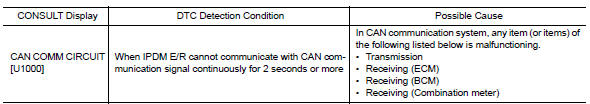
Diagnosis Procedure
1. PERFORM SELF DIAGNOSTIC RESULT
1. Turn ignition switch ON and wait for 2 second or more.
2. Check "SELF-DIAG RESULTS" of IPDM E/R.
Is "CAN COMM CIRCUIT" displayed?
YES >> Refer to LAN "Trouble Diagnosis Flow Chart".
NO >> Refer to GI "Intermittent Incident".
 IPDM E/R (Intelligent power distribution
module engine room)
IPDM E/R (Intelligent power distribution
module engine room)
Reference Value VALUES ON THE DIAGNOSIS TOOL TERMINAL LAYOUT PHYSICAL VALUES *:M/T **:CVT or A/T ...
B2098 Ignition relay on stuck
Description The ignition relay integrated in IPDM E/R is operated with ignition switch ON signal from the ignition switch. DTC Logic DTC DETECTION LOGIC Diagnosis Procedure 1. PERFORM SELF ...
Other materials:
P062F EEPROM
Description
TCM compares the calculated value stored in the flash ROM with the value
stored in TCM. If the calculated
value does not agree with the stored value, TCM judges this as a malfunction.
DTC Logic
DTC DETECTION LOGIC
DTC
Trouble diagnosis name
DTC detection condition
...
Precautions
Precaution for Supplemental Restraint System
(SRS) "AIR BAG" and "SEAT BELT PRE-TENSIONER"
The Supplemental Restraint System such as "AIR BAG" and "SEAT BELT
PRE-TENSIONER", used along
with a front seat belt, helps to reduce the risk or severity of injury to the
driver and ...
Categories
- Manuals Home
- Nissan Versa Owners Manual
- Nissan Versa Service Manual
- Video Guides
- Questions & Answers
- External Resources
- Latest Updates
- Most Popular
- Sitemap
- Search the site
- Privacy Policy
- Contact Us

0.005