
Nissan Versa (N17): B2614 ACC Relay circuit
DTC Logic
DTC DETECTION LOGIC

DTC CONFIRMATION PROCEDURE
1.PERFORM DTC CONFIRMATION PROCEDURE
1. Turn ignition switch to ACC, and wait for 1 second or more.
2. Check "Self-diagnosis result" of BCM with CONSULT.
Is DTC detected?
YES >> Go to PCS "Diagnosis Procedure".
NO >> Inspection End.
Diagnosis Procedure
Regarding Wiring Diagram information, refer to PCS "Wiring Diagram".
1.CHECK ACCESSORY RELAY CONTROL SIGNAL
Check voltage between BCM harness connector and ground.

Is the inspection result normal?
YES >> Replace BCM. Refer to BCS "Removal and Installation".
NO >> GO TO 2.
2.CHECK ACCESSORY RELAY CONTROL SIGNAL CIRCUIT
1. Turn ignition switch OFF.
2. Disconnect BCM connector and accessory relay.
3. Check continuity between BCM harness connector and accessory relay harness
connector.
4. Check continuity between BCM harness connector and ground.
Is the inspection result normal?
YES >> GO TO 3.
NO >> Repair or replace harness.
3.CHECK ACCESSORY RELAY
Refer to PCS "Component Inspection".
Is the inspection result normal?
YES >> Replace BCM. Refer to BCS "Removal and Installation".
NO >> Replace accessory relay.
Component Inspection
1.CHECK ACCESSORY RELAY
1. Turn ignition switch OFF.
2. Remove accessory relay.
3. Check the continuity between accessory relay terminals.

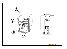
Is the inspection result normal?
YES >> Inspection End.
NO >> Replace accessory relay
 U1000 CAN Comm circuit
Description Refer to LAN "CAN COMMUNICATION SYSTEM : System Description". DTC Logic DTC DETECTION LOGIC NOTE: U1000 can be set if a module harness was disconnected and reconnected, ...

Other materials:
Security systems (if so equipped)
Your vehicle has one type of security systems:
NISSAN Vehicle Immobilizer System
NISSAN vehicle immobilizer system
The NISSAN Vehicle Immobilizer System will not
allow the engine to start without the use of a
registered key.
If the engine fails to start using a registered key
(for ex ...
Occupant classification system
OCCUPANT CLASSIFICATION SYSTEM : System Diagram
OCCUPANT CLASSIFICATION SYSTEM : System
Description
The occupant classification system (OCS) identifies different size occupants,
out of position occupants, and
detects if child seat is present in the front passenger seat. The OCS control
...
Categories
- Manuals Home
- Nissan Versa Owners Manual
- Nissan Versa Service Manual
- Video Guides
- Questions & Answers
- External Resources
- Latest Updates
- Most Popular
- Sitemap
- Search the site
- Privacy Policy
- Contact Us

0.0352