Nissan Versa (N17): B2616 Ignition relay circuit
DTC Logic
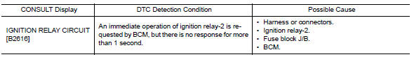
DTC DETECTION LOGIC
DTC CONFIRMATION PROCEDURE
1. PERFORM SELF DIAGNOSTIC RESULT
1. Turn ignition switch ON under the following conditions, and wait for at least 1 second.
- CVT selector lever is in the P (park) or N (neutral) position.
- Release brake pedal
2. Perform self diagnostic result.
Is DTC B2616 detected?
YES >> Refer to PCS "Diagnosis Procedure".
NO >> Inspection End.
Diagnosis Procedure
Regarding Wiring Diagram information, refer to PCS "Wiring Diagram".
1. CHECK IGNITION RELAY-2 POWER SUPPLY CIRCUIT
1. Turn ignition switch OFF.
2. Disconnect BCM connector M98.
3. Check continuity between ignition relay-2 connector J-3 terminal 1 and BCM
connector M98 terminal 99.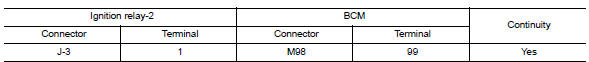
4. Check continuity between ignition relay-2 connector J-3 terminal 1 and
ground.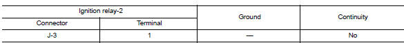
Is the inspection result normal?
YES >> GO TO 2.
NO >> Repair or replace harness or connectors.
2. CHECK IGNITION RELAY-2 GROUND CIRCUIT
1. Check continuity between ignition relay-2 connector J-3 terminal 2 and
ground.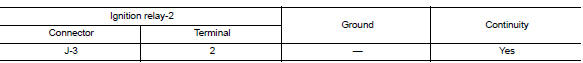
Is the inspection result normal?
YES >> GO TO 3.
NO >> Repair or replace harness or connectors.
3. CHECK IGNITION RELAY-2
Perform the relay component inspection. Refer to PCS "Component Inspection".
Is the inspection result normal?
YES >> GO TO 4.
NO >> Replace ignition relay-2.
4. CHECK IGNITION RELAY-2 POWER SUPPLY (BCM)
Check voltage between BCM connector M98 terminal 99 and ground.
Is the inspection result normal?
YES >> Refer to GI "Intermittent Incident".
NO >> Replace BCM. Refer to BCS "Removal and Installation".
Component Inspection
1.CHECK IGNITION RELAY
1. Turn ignition switch OFF.
2. Remove ignition relay.
3. Check the continuity between ignition relay terminals.
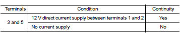
Is the inspection result normal?
YES >> Inspection End.
NO >> Replace ignition relay
 B2615 Blower relay circuit
Other materials:
Remote keyless entry system (if so equipped)
WARNING
Radio waves could adversely affect
electric medical equipment. Those who
use a pacemaker should contact the
electric medical equipment manufacturer
for the possible influences before
use.
The remote keyless entry key fob transmits
radio waves when the buttons are
pressed. ...
Front drive shaft
Exploded View
1. Circlip 2. Dust shield 3. Slide joint housing
4. Snap ring 5. Spider assembly 6. Boot band
7. Boot 8. Shaft 9. Damper band
10. Dynamic damper 11. Circlip 12. Joint sub-assembly
Wheel side
Disassembly and Assembly
DISASSEMBLY
Transaxle Side
Fix shaft with a vise.
...
Categories
- Manuals Home
- Nissan Versa Owners Manual
- Nissan Versa Service Manual
- Video Guides
- Questions & Answers
- External Resources
- Latest Updates
- Most Popular
- Sitemap
- Search the site
- Privacy Policy
- Contact Us

0.0062