Nissan Versa (N17): B Terminal circuit
Description
"B" terminal circuit supplies power to charge the battery and to operate the vehicles electrical system.
Diagnosis Procedure
Regarding Wiring Diagram information. Refer to CHG "Wiring Diagram".
1.CHECK "B" TERMINAL CONNECTION
1. Turn ignition switch OFF.
2. Check if "B" terminal is clean and tight.
Is the inspection result normal?
YES >> GO TO 2.
NO >> Repair terminal "B" connection. Confirm repair by performing complete Charging system test using the EXP-800 NI or GR8-1200 NI (if available). Refer to applicable Instruction Manual for proper testing procedures.
2.CHECK "B" TERMINAL CIRCUIT
Check voltage between generator "B" terminal and ground.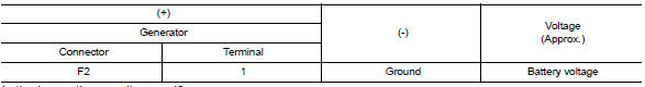
Is the inspection result normal?
YES >> GO TO 3.
NO >> Check harness for open between generator and fusible link.
3.CHECK "B" TERMINAL CONNECTION (VOLTAGE DROP TEST)
1. Start engine, then engine running at idle and warm.
2. Check voltage between battery positive terminal and generator connector
"B" terminal.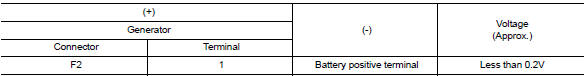
Is the inspection result normal?
YES >> "B" terminal circuit is normal. Refer to CHG "Work Flow (With EXP-800 NI or GR8-1200 NI)" or CHG "Work Flow (Without EXP-800 NI or GR8-1200 NI)".
NO >> Check harness between battery and generator for continuity.
 Power generation voltage variable
control system operation inspection
Power generation voltage variable
control system operation inspection
Diagnosis Procedure Regarding Wiring Diagram information. Refer to CHG "Wiring Diagram". CAUTION: When performing this inspection, always use a charged battery that has completed the ...
L Terminal circuit (open)
Description The "L" terminal circuit controls the charge warning lamp. The charge warning lamp turns ON when the ignition switch is set to ON or START. When the generator is providing sufficient ...
Other materials:
Engine oil
Inspection
ENGINE OIL LEVEL
Park vehicle on a level surface, wait 10 minutes before checking the
engine oil level.
Pull out oil level gauge and wipe it clean.
Insert oil level gauge and make sure the engine oil level is within
the range (A) as shown.
If it is out of range, adjust it. ...
P0982 Shift solenoid D
DTC Logic
DTC DETECTION LOGIC
DTC
Trouble diagnosis name
DTC detection condition
Possible causes
P0982
Shift Solenoid D Control Circuit
Low
The following diagnosis conditions
are met, and the current
monitor reading of the TCM
high clutch/low & revers ...
Categories
- Manuals Home
- Nissan Versa Owners Manual
- Nissan Versa Service Manual
- Video Guides
- Questions & Answers
- External Resources
- Latest Updates
- Most Popular
- Sitemap
- Search the site
- Privacy Policy
- Contact Us

0.0048