Nissan Versa (N17): Power generation voltage variable control system operation inspection
Diagnosis Procedure
Regarding Wiring Diagram information. Refer to CHG "Wiring Diagram".
CAUTION: When performing this inspection, always use a charged battery that has completed the battery inspection.
(When the charging rate of the battery is low, the response speed of the voltage change will become slow. This can cause an incorrect inspection.)
1.CHECK ECM (CONSULT)
Perform ECM self-diagnosis with CONSULT. Refer to EC "CONSULT Function".
Self-diagnostic results content
No malfunction detected>> GO TO 2.
Malfunction detected>> Check applicable parts, and repair or replace corresponding parts.
2.CHECK OPERATION OF POWER GENERATION VOLTAGE VARIABLE CONTROL SYSTEM
1. Connect CONSULT and start the engine.
2. The selector lever is in "P" or "N" position and all of the electric loads and A/C, etc. are turned OFF.
3. Select "ALTERNATOR DUTY" in "Active Test" of "ENGINE", and then check the value of "BATTERY VOLT" monitor when DUTY value of "DUTY" is set to 40.0 %.
"BATTERY VOLT" 2 seconds after setting the DUTY value of "ALTERNATOR DUTY" to 40.0 % : 12 - 13.6 V
4. Check the value of "BATTERY VOLT" monitor when DUTY value of "DUTY" is set to 80.0%.
"BATTERY VOLT" 20 seconds after setting the DUTY value of "ALTERNATOR DUTY" to 80.0 % : +0.5 V or more against the value of "BATTERY VOLT" monitor when DUTY value is 40.0 %
Is the inspection result normal?
YES >> Inspection End.
NO >> GO TO 3.
3.CHECK IPDM E/R (CONSULT)
Perform IPDM E/R self-diagnosis with CONSULT. Refer to PCS "CONSULT Function (IPDM E/R)".
Is the inspection result normal?
No malfunction detected>> GO TO 4.
Malfunction detected>> Check applicable parts, and repair or replace corresponding parts.
4.CHECK HARNESS BETWEEN GENERATOR AND IPDM E/R
1. Turn ignition switch OFF.
2. Disconnect generator connector and IPDM E/R connector.
3. Check continuity between generator harness connector and IPDM E/R harness
connector.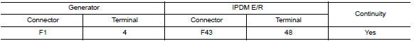
4. Check continuity between generator harness connector and ground.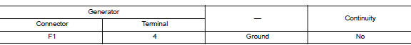
Is the inspection result normal?
YES >> Replace IPDM E/R. Refer to PCS"Removal and Installation".
NO >> Repair harness or connectors between IPDM E/R and generator.
 Charging system preliminary inspection
Diagnosis Procedure 1.CHECK BATTERY TERMINALS CONNECTION Check if battery terminals are clean and tight. Is the inspection result normal? YES >> GO TO 2. NO >> Repair battery termin ...
B Terminal circuit
Description "B" terminal circuit supplies power to charge the battery and to operate the vehicles electrical system. Diagnosis Procedure Regarding Wiring Diagram information. Refer to CHG "W ...
Other materials:
Diagnosis system (EPS control unit)
CONSULT Function
FUNCTION
CONSULT can display each diagnostic item using the diagnostic test modes
shown following.
*: The following diagnosis information is erased by erasing.
DTC
Freeze frame data (FFD)
ECU IDENTIFICATION
Displays the part number stored in the con ...
Rear RH
REAR RH : Component Function Check
1.CHECK FUNCTION
Select DOOR LOCK of BCM using CONSULT.
Select DOOR LOCK in ACTIVE TEST mode.
Touch ALL LOCK or ALL UNLK to check that it works normally.
Is the inspection result normal?
YES >> Door lock actuator is OK.
NO >> Refer to DL ...
Categories
- Manuals Home
- Nissan Versa Owners Manual
- Nissan Versa Service Manual
- Video Guides
- Questions & Answers
- External Resources
- Latest Updates
- Most Popular
- Sitemap
- Search the site
- Privacy Policy
- Contact Us

0.0061