Nissan Versa (N17): Charging system preliminary inspection
Diagnosis Procedure
1.CHECK BATTERY TERMINALS CONNECTION
Check if battery terminals are clean and tight.
Is the inspection result normal?
YES >> GO TO 2.
NO >> Repair battery terminal connection. Confirm repair by performing complete Charging system test using EXP-800 NI or GR8-1200 NI (if available). Refer to the applicable Instruction Manual for proper testing procedures.
2.CHECK FUSE
Check for blown fuse and fusible link.
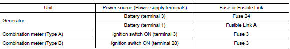
Is the inspection result normal?
YES >> GO TO 3.
NO >> Replace the blown fuse or fusible link after repairing the affected circuit.
3.CHECK GENERATOR GROUND TERMINAL CONNECTION
Check if connector F4 terminal 5 is clean.
Is the inspection result normal?
YES >> GO TO 4.
NO >> Repair connection.
4.CHECK DRIVE BELT TENSION
Check drive belt tension. Refer to EM "Inspection".
Is the inspection result normal?
YES >> Inspection End.
NO >> Repair as needed.
 Diagnosis and repair workflow
Power generation voltage variable
control system operation inspection
Diagnosis Procedure Regarding Wiring Diagram information. Refer to CHG "Wiring Diagram". CAUTION: When performing this inspection, always use a charged battery that has completed the ...
Other materials:
Jump starting
To start your engine with a booster battery, the
instructions and precautions below must be followed.
WARNING
If done incorrectly, jump starting can
lead to a battery explosion, resulting in
severe injury or death. It could also
damage your vehicle.
Explosive hydrogen gas is always pre ...
Positive crankcase ventilation
Inspection
1.CHECK PCV VALVE
With engine running at idle, remove PCV valve from rocker cover. A
properly working valve makes a hissing noise as air passes through
it. A strong vacuum should be felt immediately when a finger is
placed over valve inlet.
Is the inspection result normal?
YES &g ...
Categories
- Manuals Home
- Nissan Versa Owners Manual
- Nissan Versa Service Manual
- Video Guides
- Questions & Answers
- External Resources
- Latest Updates
- Most Popular
- Sitemap
- Search the site
- Privacy Policy
- Contact Us

0.0049