Nissan Versa (N17): B terminal circuit
Description
Terminal "B" is constantly supplied with battery power.
Diagnosis Procedure
Regarding Wiring Diagram information, refer to STR, "Wiring Diagram - With Intelligent Key System" or STR, "Wiring Diagram - Without Intelligent Key System".
CAUTION: Perform diagnosis under the condition that the engine cannot start by the following procedure.
- Remove fuel pump fuse.
- Crank or start the engine (where possible) until the fuel pressure is released.
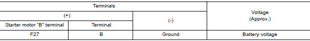
1.CHECK "B" TERMINAL CIRCUIT
- Turn ignition switch OFF.
- Check that starter motor B" terminal connection is clean and tight.
- Check voltage between starter motor connector F27 and ground.
Is the inspection result normal?
YES >> GO TO 2.
NO >> Check harness between battery and starter motor for open circuit.
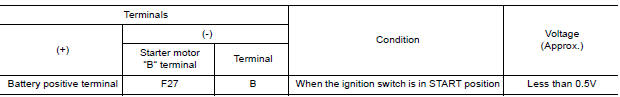
2.CHECK BATTERY CABLE CONNECTION STATUS (VOLTAGE DROP TEST)
- Shift selector lever to P (Park) or N (Neutral) position.
- Check voltage between battery positive terminal and starter motor B
terminal.
Is the inspection result normal?
YES >> GO TO 3.
NO >> Check harness between the battery and starter motor for continuity.
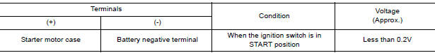
3.CHECK GROUND CIRCUIT STATUS (VOLTAGE DROP TEST)
- Shift selector lever to P (Park) or N (Neutral) position.
- Check voltage between starter motor case and battery negative terminal.
Is the inspection result normal?
YES >> "B" terminal circuit is OK. Further inspection is necessary. Refer to STR, "Work Flow (With GR-1200 NI)" or STR, "Work Flow (Without GR8-1200 NI)".
NO >> Check the starter motor case to engine mounting for high resistance.
 Diagnosis and repair workflow
S connector circuit
Description The starter motor magnetic switch is supplied with power when the ignition switch is turned to the START position while the selector lever is in the P (Park) or N (Neutral) position. ...
Other materials:
Exterior front
1. Engine hood
2. Windshield
3. Wiper and washer switch
4. Power windows (if so equipped)
5. Door locks. NISSAN Intelligent Key
(if so equipped). Key fob (if so equipped). Keys
6. Mirrors
7. Tire pressure. Flat tire. Tire chains
8. Headlight and turn signal switch. Replacing bulbs
9. Fo ...
Push-button ignition switch (if so equipped)
WARNING
Do not operate the push-button ignition
switch while driving the vehicle except in
an emergency. (The engine will stop when
the ignition switch is pushed 3 consecutive
times in quick succession or the ignition
switch is pushed and held for more
than 2 seconds.) If the engine stops ...
Categories
- Manuals Home
- Nissan Versa Owners Manual
- Nissan Versa Service Manual
- Video Guides
- Questions & Answers
- External Resources
- Latest Updates
- Most Popular
- Sitemap
- Search the site
- Privacy Policy
- Contact Us

0.0046