Nissan Versa (N17): BCM Branch line circuit
Diagnosis Procedure
1.CHECK CONNECTOR
1. Turn the ignition switch OFF.
2. Disconnect the battery cable from the negative terminal.
3. Check the terminals and connectors of the BCM for damage, bend and loose connection (unit side and connector side).
Is the inspection result normal?
YES >> GO TO 2.
NO >> Repair the terminal and connector.
2.CHECK HARNESS FOR OPEN CIRCUIT
1. Disconnect the connector of BCM.
2. Check the resistance between the BCM harness connector terminals.
- Models with Intelligent Key system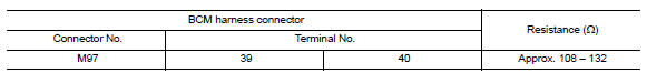
- Models without Intelligent Key system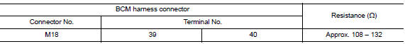
Is the measurement value within the specification?
YES >> GO TO 3.
NO >> Repair the BCM branch line.
3.CHECK POWER SUPPLY AND GROUND CIRCUIT
Check the power supply and the ground circuit of the BCM. Refer to the following.
- Models with Intelligent Key system: BCS "Diagnosis Procedure"
- Models without Intelligent Key system: BCS "Diagnosis Procedure"
Is the inspection result normal?
YES (Present error)>>Replace the BCM. Refer to the following.
- Models with Intelligent Key system: BCS "Removal and Installation"
- Models without Intelligent Key system: BCS "Removal and Installation"
YES (Past error)>>Error was detected in the BCM branch line.
NO >> Repair the power supply and the ground circuit.
 STRG Branch line circuit
Diagnosis Procedure 1.CHECK CONNECTOR 1. Turn the ignition switch OFF. 2. Disconnect the battery cable from the negative terminal. 3. Check the terminals and connectors of the steering angle senso ...
CAN Communication circuit
Diagnosis Procedure 1.CONNECTOR INSPECTION 1. Turn the ignition switch OFF. 2. Disconnect the battery cable from the negative terminal. 3. Disconnect all the unit connectors on CAN communication s ...
Other materials:
Line pressure test
Work Procedure
INSPECTION
Check the engine oil level. Replenish if necessary. Refer to LU
"Inspection".
Check for CVT fluid leaks. Refer to TM "Inspection".
Drive for about 10 minutes to warm up the vehicle so that the CVT fluid
temperature is 50 to 80C (122 to
...
The braking distance is long
Diagnosis Procedure
CAUTION:
The stopping distance on slippery road surfaces might be longer with the ABS
operating than when
the ABS is not operating.
1.CHECK ABS FUNCTION
Turn ignition switch OFF.
Disconnect ABS actuator and electric unit (control unit) connector to
deactivate ABS ...
Categories
- Manuals Home
- Nissan Versa Owners Manual
- Nissan Versa Service Manual
- Video Guides
- Questions & Answers
- External Resources
- Latest Updates
- Most Popular
- Sitemap
- Search the site
- Privacy Policy
- Contact Us

0.0052