Nissan Versa (N17): STRG Branch line circuit
Diagnosis Procedure
1.CHECK CONNECTOR
1. Turn the ignition switch OFF.
2. Disconnect the battery cable from the negative terminal.
3. Check the terminals and connectors of the steering angle sensor for damage, bend and loose connection (unit side and connector side).
Is the inspection result normal?
YES >> GO TO 2.
NO >> Repair the terminal and connector.
2.CHECK HARNESS FOR OPEN CIRCUIT
1. Disconnect the connector of steering angle sensor.
2. Check the resistance between the steering angle sensor harness connector
terminals.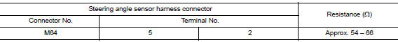
Is the measurement value within the specification?
YES >> GO TO 3.
NO >> Repair the steering angle sensor branch line.
3.CHECK POWER SUPPLY AND GROUND CIRCUIT
Check the power supply and the ground circuit of the steering angle sensor. Refer to BRC "Wiring Diagram".
Is the inspection result normal?
YES (Present error)>>Replace the steering angle sensor. Refer to BRC "Removal and Installation".
YES (Past error)>>Error was detected in the steering angle sensor branch line.
NO >> Repair the power supply and the ground circuit.
 M&A Branch line circuit
Diagnosis Procedure 1.CHECK CONNECTOR 1. Turn the ignition switch OFF. 2. Disconnect the battery cable from the negative terminal. 3. Check the terminals and connectors of the combination meter fo ...
BCM Branch line circuit
Diagnosis Procedure 1.CHECK CONNECTOR 1. Turn the ignition switch OFF. 2. Disconnect the battery cable from the negative terminal. 3. Check the terminals and connectors of the BCM for damage, bend ...
Other materials:
Drive belt idler pulley
Exploded View
1. Generator bracket 2. Center shaft 3. Spacer
4. Adjusting bolt 5. Washer 6. Idler pulley
7. Plate
Removal and Installation
REMOVAL
Remove the fender protector (RH).
Remove the air duct inlet assembly.
Remove drive belt.
Remove the lock nut, and then remove the pl ...
Front oil seal
FRONT OIL SEAL : Removal and Installation
REMOVAL
1. Remove the following parts.
Remove wheel and tire.
Front fender protector (RH).
Drive belt.
Crankshaft pulley.
2. Remove front oil seal with ...
Categories
- Manuals Home
- Nissan Versa Owners Manual
- Nissan Versa Service Manual
- Video Guides
- Questions & Answers
- External Resources
- Latest Updates
- Most Popular
- Sitemap
- Search the site
- Privacy Policy
- Contact Us

0.0053