Nissan Versa (N17): M&A Branch line circuit
Diagnosis Procedure
1.CHECK CONNECTOR
1. Turn the ignition switch OFF.
2. Disconnect the battery cable from the negative terminal.
3. Check the terminals and connectors of the combination meter for damage, bend and loose connection (unit side and connector side).
Is the inspection result normal?
YES >> GO TO 2.
NO >> Repair the terminal and connector.
2.CHECK HARNESS FOR OPEN CIRCUIT
1. Disconnect the connector of combination meter.
2. Check the resistance between the combination meter harness connector terminals.
NOTE: Check the vehicle type confirm the service information. Refer to MWI "Information".
- Models with Type A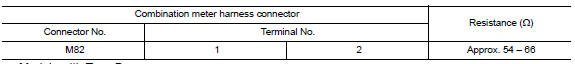
- Models with Type B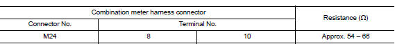
Is the measurement value within the specification?
YES >> GO TO 3.
NO >> Repair the combination meter branch line.
3.CHECK POWER SUPPLY AND GROUND CIRCUIT
Check the power supply and the ground circuit of the combination meter. Refer to the following.
- TYPE A: MWI "COMBINATION METER : Diagnosis Procedure"
- TYPE B: MWI"COMBINATION METER : Diagnosis Procedure"
Is the inspection result normal?
YES (Present error)>>Replace the combination meter. Refer to the following.
- TYPE A: MWI "Removal and Installation"
- TYPE B: MWI "Removal and Installation"
YES (Past error)>>Error was detected in the combination meter branch line.
NO >> Repair the power supply and the ground circuit.
 EPS Branch line circuit
Diagnosis Procedure 1.CHECK CONNECTOR 1. Turn the ignition switch OFF. 2. Disconnect the battery cable from the negative terminal. 3. Check the terminals and connectors of the EPS control unit f ...
STRG Branch line circuit
Diagnosis Procedure 1.CHECK CONNECTOR 1. Turn the ignition switch OFF. 2. Disconnect the battery cable from the negative terminal. 3. Check the terminals and connectors of the steering angle senso ...
Other materials:
Exterior front
1. Engine hood
2. Windshield
3. Wiper and washer switch
4. Power windows (if so equipped)
5. Door locks. NISSAN Intelligent Key
(if so equipped). Key fob (if so equipped). Keys
6. Mirrors
7. Tire pressure. Flat tire. Tire chains
8. Headlight and turn signal switch. Replacing bulbs
9. Fo ...
Power steering fluid
Check the fluid level in the reservoir.
The fluid level should be checked when the fluid
is cold at fluid temperatures of 32 to 86ºF (0 to
30ºC). The fluid level can be checked with the
level gauge which is attached to the cap. To
check the fluid level, remove the cap. The fluid ...
Categories
- Manuals Home
- Nissan Versa Owners Manual
- Nissan Versa Service Manual
- Video Guides
- Questions & Answers
- External Resources
- Latest Updates
- Most Popular
- Sitemap
- Search the site
- Privacy Policy
- Contact Us

0.0046