Nissan Versa (N17): Blower fan resistor
Exploded View
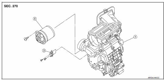
1. A/C unit assembly 2. Blower motor 3. Blower fan resistor
Removal and Installation
REMOVAL
- Remove instrument panel assembly. Refer to IP "Removal and Installation".
- Disconnect harness connector from the blower fan resistor.
- Remove screws and blower fan resistor.
INSTALLATION
Installation is in the reverse order of removal.
DOOR CABLE
Exploded View
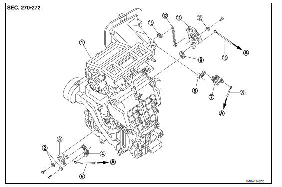
1. A/C unit assembly 2. Plate 3. Air mix door link 2 4. Air mix door link 1 5. Air mix door cable 6. Intake door lever 7. Intake door link 8. Intake door cable 9. Foot door lever 10. Mode door cable 11. Main link 12. Ventilator door rod 13. Ventilator door lever A. To A/C control
 Refrigerant pressure sensor
Removal and Installation for Refrigerant Pressure Sensor REMOVAL CAUTION: Do not damage the condenser fins. Perform lubricant return operation before each refrigeration system disassembly. ...
Intake door cable
INTAKE DOOR CABLE : Removal and Installation REMOVAL Remove instrument panel assembly. Refer to IP "Removal and Installation". Disconnect intake door cable from A/C control. Disc ...
Other materials:
Cleaning exterior
In order to maintain the appearance of your vehicle,
it is important to take proper care of it.
To protect the paint surfaces, please wash your
vehicle as soon as you can:
After a rainfall to prevent possible damage
from acid rain.
After driving on coastal roads.
When contaminants suc ...
Positive crankcase ventilation
Inspection
1.CHECK PCV VALVE
With engine running at idle, remove PCV valve from rocker cover. A
properly working valve makes a hissing noise as air passes through
it. A strong vacuum should be felt immediately when a finger is
placed over valve inlet.
Is the inspection result normal?
YES &g ...
Categories
- Manuals Home
- Nissan Versa Owners Manual
- Nissan Versa Service Manual
- Video Guides
- Questions & Answers
- External Resources
- Latest Updates
- Most Popular
- Sitemap
- Search the site
- Privacy Policy
- Contact Us

0.0213