Nissan Versa (N17): Refrigerant pressure sensor
Removal and Installation for Refrigerant Pressure Sensor
REMOVAL
CAUTION:
- Do not damage the condenser fins.
- Perform lubricant return operation before each refrigeration
system disassembly. However, if a large amount of refrigerant
or lubricant is detected, do not perform lubricant return operation.
Refer to HA "Perform Oil Return Operation".
- Move air guide aside.
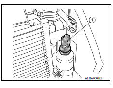
- Disconnect the harness connector from the refrigerant pressure sensor.
- Remove the refrigerant pressure sensor (1) from the liquid tank on the condenser.
INSTALLATION
Installation is in the reverse order of removal.
CAUTION:
- Replace O-ring with new one. Then apply compressor oil to them when installing.
- Check for leakages when recharging refrigerant. Refer to HA "Leak Test".
 Front air control
Exploded View 1. Mode door cable 2. Illumination bulb 3. Air mix door cable 4. Front air control 5. Intake door cable 6. Intake door lever knob 7. Control panel bezel 8. Mode dial 9. Temperat ...
Blower fan resistor
Exploded View 1. A/C unit assembly 2. Blower motor 3. Blower fan resistor Removal and Installation REMOVAL Remove instrument panel assembly. Refer to IP "Removal and Installation&qu ...
Other materials:
Rear window defroster switch
To defrost the rear window glass, start the engine
and push the rear window defroster switch on.
The rear window defroster indicator light on the
switch comes on. Push the switch again to turn
the defroster off.
The rear window defroster automatically turns off
after approximately 15 m ...
P2858 Clutch B pressure
DTC Logic
DTC DETECTION LOGIC
DTC
Trouble diagnosis name
DTC detection condition
Possible causes
P2858
Clutch B pressure engagement
performance
The auxiliary gearbox gear ratio is 2.232 or
more for the auxiliary gearbox 2GR ratio continuously
for 5 seconds ...
Categories
- Manuals Home
- Nissan Versa Owners Manual
- Nissan Versa Service Manual
- Video Guides
- Questions & Answers
- External Resources
- Latest Updates
- Most Popular
- Sitemap
- Search the site
- Privacy Policy
- Contact Us

0.0054