Nissan Versa (N17): Preparation
Special Service Tools
The actual shapes of KentMoore tools may differ from those of special service tools illustrated here.
| Tool number (KentMoore No.) Tool name | Description |
KV10111100
(J37228)
Seal cutter  |
Removing oil pan (lower and upper) etc. |
KV10116200
(J26336B)
Valve spring compressor
1. KV10115900
(J2633620)
Attachment
2. KV10109220
( - )
Adapter 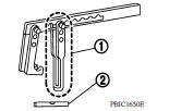 |
Disassembling and assembling valve mechanism Part (1) is a component of KV10116200, but Part (2) is not so. |
KV10112100
(BT8653A)
Angle wrench  |
Tightening bolts for main bearing cap, cylinder head, etc. |
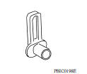
KV10117100
( - )
Heated oxygen sensor wrench
 |
Loosening or tightening heated oxygen sensor 1 For 22 mm (0.87 in) width hexagon nut |
KV10107902
(J38959)
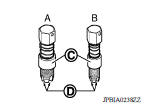
Valve oil seal puller  |
Removing valve oil seal |
KV10115600
(J38958)
Valve oil seal drift  |
Installing valve oil seal
Use side A.
a: 20 (0.79) dia. d: 8 (0.31) dia. b: 13 (0.51) dia. e: 10.7 (0.421) c: 10.3 (0.406) dia. f: 5 (0.20) Unit: mm (in) |
EM03470000
(J8037)
Piston ring compressor  |
Installing piston assembly into cylinder bore |
ST16610001
(J23907)
Pulley puller  |
Removing pilot converter |
KV11103000
( - )
Pulley puller  |
Removing crankshaft pulley |
KV11105210
(J44716)
Stopper plate 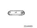 |
Holding drive plate and flywheel static |
Commercial Service Tools
| Tool name | Description |
Power tool 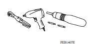 |
Loosening nuts, screws and bolts |
Quick connector release
 |
Removing fuel tube quick connectors in engine room |
Spark plug wrench 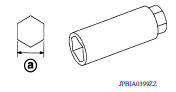 |
Removing and installing spark plug a: 14 mm (0.55 in) |
Pulley holder  |
Crankshaft pulley removing and installing |
Valve seat cutter set  |
Finishing valve seat dimensions |
Piston ring expander
 |
Removing and installing piston ring |
Valve guide drift 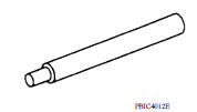 |
Removing and installing valve guide |
Valve guide reamer 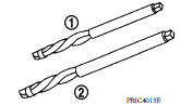 |
(1): Reaming valve guide inner hole (2): Reaming hole for oversize valve guide |
(J4389718)
(J4389712)
Oxygen sensor thread cleaner
 |
Reconditioning the exhaust system threads before installing a new air fuel ratio sensor (Use with antiseize lubricant shown below.) A: [18 mm (0.71 in) dia.] for zirconia heated oxygen sensor B: [12 mm (0.47 in) dia.] for titania heated oxygen sensor C: Mating surface shave cylinder D: Flutes |
Acoustic tension gauge
 |
Checking drive belt tension |
Antiseize lubricant (Permatex 133AR
or equivalent meeting MIL specification
MILA907)  |
Lubricating oxygen sensor thread cleaning tool when reconditioning exhaust system threads |
Manual lift table caddy
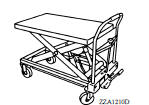 |
Removing and installing engine |
1. Compression gauge
2. Adapter 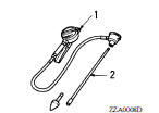 |
Checking compression pressure |
Tube presser  |
Pressing the tube of liquid gasket |
 Precautions
Camshaft valve clearance
Inspection and Adjustment INSPECTION Perform inspection as follows after removal, replacement or installation of camshaft or valverelated parts, or if there are unusual engine conditions regardin ...
Other materials:
Compression pressure
Inspection
Warm up engine and then turn it off.
Release fuel pressure.
Remove ignition coil and spark plug from each cylinder.
Connect engine tachometer (not required in use of CONSULT).
Install compression gauge (B) with an adapter (A) (commercial
service tool) onto spark plug hole.
...
Control linkage
Exploded View
1. Shifter lever A 2. Selector lever 3. Selector cable
4. Shifter cable 5. Cable mounting bracket 6. Tapping bolt
7. Bracket 8. Grommet 9. M/T shift selector assembly
10. Shift selector 11. Shift selector handle
Removal and Installation
REMOVAL
Move the shift selector to ...
Categories
- Manuals Home
- Nissan Versa Owners Manual
- Nissan Versa Service Manual
- Video Guides
- Questions & Answers
- External Resources
- Latest Updates
- Most Popular
- Sitemap
- Search the site
- Privacy Policy
- Contact Us

0.0085