Nissan Versa (N17): Clutch master cylinder
Exploded View
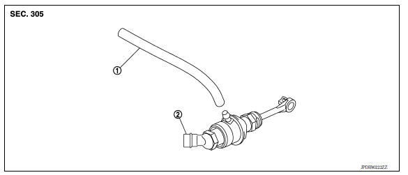
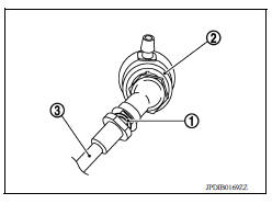
1. Reservoir hose 2. Master cylinder
Removal and Installation
CAUTION:
- Do not spill clutch fluid onto painted surfaces. If fluid spills, wipe up immediately and wash the affected area with water.
- Do not disassemble clutch master cylinder.
NOTE: When removing components such as hoses, tubes/lines, etc., cap or plug openings to prevent fluid from spilling.
REMOVAL
- Remove battery. Refer to PG, "Removal and Installation".
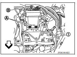
- Remove IPDM E/R bracket bolts (A) and nut (B).
- Remove IPDM E/R bracket (1).
 : Front
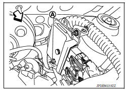
4. Remove ECM bracket nuts (A).
 : Front
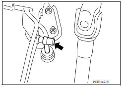
5. Remove master cylinder rod end (
 ) from clutch pedal.
6. Use one of the following methods to remove hose from master cylinder.
- Drain clutch fluid from reservoir tank and remove hose. Refer to CL, "Draining".
- Remove hose from master cylinder.
7. Pull up the lock pin (1) from connector of master cylinder (2) and separate clutch tube (3).
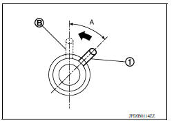
8. Rotate master cylinder clockwise by 45 degrees and then remove master cylinder from the vehicle.
INSTALLATION
CAUTION: Do not spill clutch fluid onto painted surfaces. If fluid spills, wipe up immediately and wash the affected area with water.
- With the nipple (1) rotated clockwise by 45 degrees, insert clutch master cylinder into the mounting hole. Rotate the clutch master cylinder counterclockwise by 45 degrees (A) as shown to secure it. At this time, nipple is in the upward (B).
- Install master cylinder rod end to clutch pedal.
CAUTION: Press master cylinder rod end into clutch pedal until it stops.
- Install reservoir hose to master cylinder.
- Press down the lock pin into connector of master cylinder until it stops.
- Install clutch tube into connector of master cylinder until it stops.
- Fill with clutch fluid and bleed clutch hydraulic system. Refer to CL "Refilling".
- Installation of the remaining components is in the reverse order of removal.
Inspection and Adjustment
INSPECTION AFTER INSTALLATION
Check for fluid leakage and check the fluid level. Refer to CL, "Inspection".
 Clutch pedal
Exploded View 1. Clutch pedal 2. Pedal stopper rubber 3. Pedal pad 4. Clip 5. Clutch interlock switch Removal and Installation REMOVAL Remove the instrument lower panel LH. Refer to IP, ...
Clutch piping
Exploded View 1. CSC (Concentric Slave Cylinder) 2. Clutch tube 3. Clutch damper 4. Bracket 5. Master cylinder Hydraulic Layout 1. Clutch tube 2. Lock pin 3. CSC (concentric slave cylinder ...
Other materials:
EVAP canister
Exploded View
1. EVAP control system pressure sensor 2. O-ring 3. EVAP canister
4. Hose clamp 5. EVAP canister purge hose 6. EVAP vent line
7. O-ring 8. EVAP canister vent control valve 9. EVAP canister vent control
valve
hose
A. Mount to vehicle bracket
Removal and Installation
NOTE: ...
U0073 Communication bus A off
Description
CAN (Controller Area Network) is a serial communication line for real-time
application. It is an on-vehicle multiplex
communication line with high data communication speed and excellent malfunction
detection ability.
Many electronic control units are equipped onto a vehicle, an ...
Categories
- Manuals Home
- Nissan Versa Owners Manual
- Nissan Versa Service Manual
- Video Guides
- Questions & Answers
- External Resources
- Latest Updates
- Most Popular
- Sitemap
- Search the site
- Privacy Policy
- Contact Us

0.0295