Nissan Versa (N17): Combination switch
Exploded View
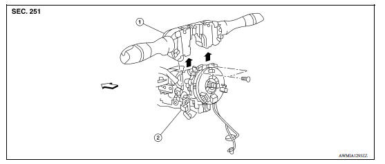
1. Combination switch 2. Combination switch harness connector
![]() Front
Front
Removal and Installation
CAUTION:
- Before servicing, disconnect both battery terminals and wait at least three minutes.
- Do not use air tools or electric tools for servicing.
REMOVAL
1. Disconnect positive and negative battery terminals. Refer to PG "Removal and Installation".
2. Remove the steering column covers. Refer to IP "Removal and Installation".
3. Rotate steering wheel clockwise to access first combination switch bolt then remove bolt.
4. Rotate steering wheel counter-clockwise to access second combination switch bolt.
5. Remove bolt, disconnect the harness connectors from the combination switch and remove.
INSTALLATION
Installation is in the reverse order of removal.
CAUTION:
- After the work is completed, make sure no system malfunction is detected by air bag warning lamp.
- In case a malfunction is detected by the air bag warning lamp, reset with the self-diagnosis function and delete the memory with CONSULT.
- If a malfunction is still detected after the above operation,
perform self-diagnosis to repair malfunctions.
Refer to SRC "SRS Operation Check".
 Front fog lamp
Exploded View 1. Front fog lamp bulb 2. Front fog lamp 3. Front bumper fascia 4. Front fog lamp finisher ...
Hazard switch
Exploded View 1. Cluster lid C 2. Hazard switch Pawl Removal and Installation REMOVAL 1. Remove the cluster lid C. Refer to IP "Removal and Installation". 2. While pressing pawls, ...
Other materials:
Oil pan (lower)
Exploded View
1. Rear oil seal 2. Oring 3. Oil pan (upper) 4. Oil pump chain tensioner
(for oil pump drive chain) 5. Oil pump drive chain 6. Crankshaft key 7.
Crankshaft sprocket 8. Oil pump sprocket 9. Oil pump 10. Oring 11. Oring 12.
Oil pan drain plug 13. Drain plug washer 14. Oil pan ...
Key interlock cable
Exploded View
1. A/T shift selector assembly 2. Key interlock cable A: Key cylinder
B: Lock plate C: Clip
Removal and Installation
CAUTION:
Always apply the parking brake before performing removal and installation.
REMOVAL
Move the shift selector to the "N" position.
Remove the s ...
Categories
- Manuals Home
- Nissan Versa Owners Manual
- Nissan Versa Service Manual
- Video Guides
- Questions & Answers
- External Resources
- Latest Updates
- Most Popular
- Sitemap
- Search the site
- Privacy Policy
- Contact Us

0.0046