Nissan Versa (N17): Front fog lamp
Exploded View
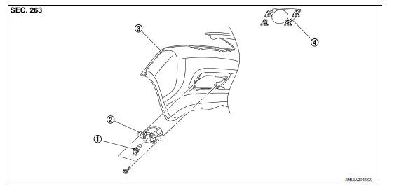
1. Front fog lamp bulb 2. Front fog lamp 3. Front bumper fascia 4. Front fog lamp finisher
Removal and Installation
REMOVAL
1. Remove the fender protector. Refer to EXT "Removal and Installation".
2. Disconnect the harness connector from the front fog lamp.
3. Remove the screws and front fog lamp.
INSTALLATION
Installation is in the reverse order of removal.
NOTE: After installation, perform fog lamp aiming adjustment procedure. Refer to EXL "Aiming Adjustment Procedure".
Bulb Replacement
WARNING: Do not touch bulb with your hand while it is on or right after being turned off. Burning may result.
CAUTION:
- Disconnect the battery negative terminal or remove power circuit fuse while performing the operation.
- Do not touch the glass surface of the bulb with bare hands or allow oil or grease to get on it to prevent damage to the bulb.
- Do not leave bulb out of lamp reflector for a long time because dust, moisture smoke, etc. may affect the performance of lamp. When replacing bulb, be sure to replace it with new one.
FRONT FOG LAMP BULB
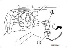
Removal
1. Remove the fender protector. Refer to EXT "Removal and Installation".
2. Disconnect the harness connector (1) from front fog lamp bulb.
3. Rotate the bulb (2) counterclockwise and remove.
Installation
Installation is in the reverse order of removal.
CAUTION: After installing the bulb, install the bulb socket securely for watertightness.
 Front combination lamp
Exploded View 1. Front combination lamp (LH) ...
Combination switch
Exploded View 1. Combination switch 2. Combination switch harness connector Front Removal and Installation CAUTION: Before servicing, disconnect both battery terminals and wait at leas ...
Other materials:
Oil pan (lower)
Exploded View
1. Rear oil seal 2. Oring 3. Oil pan (upper) 4. Oil pump chain tensioner
(for oil pump drive chain) 5. Oil pump drive chain 6. Crankshaft key 7.
Crankshaft sprocket 8. Oil pump sprocket 9. Oil pump 10. Oring 11. Oring 12.
Oil pan drain plug 13. Drain plug washer 14. Oil pan ...
Service data and specifications
(sds)
General Specification
GENERAL SPECIFICATIONS
Engine type
HR16DE
Cylinder arrangement
Inline 4
Displacement &nbs ...
Categories
- Manuals Home
- Nissan Versa Owners Manual
- Nissan Versa Service Manual
- Video Guides
- Questions & Answers
- External Resources
- Latest Updates
- Most Popular
- Sitemap
- Search the site
- Privacy Policy
- Contact Us

0.0062